Ask Question, Ask an Expert

+61-413 786 465

info@mywordsolution.com

Ask Electrical & Electronics Expert

1. Introduction

Intelligent homes are becoming increasingly popular as cost/performance ratio of microcontrollers is continuously dropping.  These systems incorporate a variety of transducers to detect and transmit status of the home to a supervisory microcomputer. Heating, lighting, security and other parameters are usually controlled by the microcomputer to give a comfortable and safe environment for the residents.

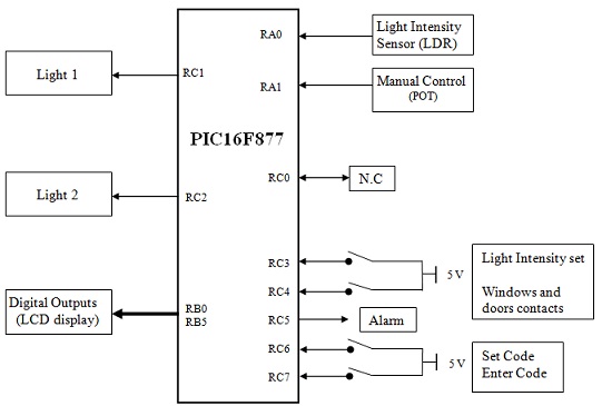
The block diagram of a simple home automation system is demonstrated below:

1242_Block diagram of automation system.jpg

2. Input and output connections

Details of connections to the microcontroller input and output ports are describeed below:

Analogue inputs:

Light Intensity Sensor (LDR) is connected to channel 0 of ADC (RA0).
Manual Control (potentiometer) is connected to channel 1 of ADC (RA1).

Analogue outputs:

Intensity of light emitted by the LED is controlled by PWM1 output (RC1).
Intensity of light emitted by the LED is controlled by PWM2 output (RC2).

Digital outputs:

LEDs connected to RC5 is used specify that a security link is broken.
RB0-RB5 outputs are connected to LCD.

Digital inputs:

RC3 switch is used to set desired ambient light on RC1 (light 1).
All window and door contacts are wire OR-ed and connected to RC4 input.
RC6 switch is used to increment security code from 0-9
RC7 is used to enter any of the three digit security code.

Table below shows the function of each bit of PORTC.
Bit number      Connection               Function
0                      Not used                    X
1                  PWM1 output               Controlled by Potentiometer (POT)
2                  PWM2 output               Controlled by LDR
3                 Sets light intensity         When held high, the desired ambient light 1 can be set
4                 Security loop                 High indicates a security breach
5                 Alarm                           Flashing LED
6                 Security code entry        High-Low transition increments code by one
7                  Enter code                   High-low transition enters one of 3 security digits

3. Objective:

To develop a ‘C’ program to emulate the intelligent home and evaluate its operation using E-BLOCK boards in the T5/03 Embedded Systems laboratory.

4. Purpose:

1. To prepare a structured and annotated ‘C’ program.
2. To provide evidence of the development of each stage of the program. This will consist of producing a logbook and a formal report.
3. To introduce new ideas or improvements to the system.

5. Tasks

The computer performs the following tasks.

1. The intensity of two lights is controlled either manually from potentiometer (dimmer mode) or automatically by measuring the intensity of ambient light using the LDR and adjusting the light output.

a) The intensity of LED connected to RC1 is adjusted by potentiometer. Press and hold RC3 switch and adjust the potentiometer from 0-5 V and show the set intensity on first line one of the LCD. The LED should light up to the required intensity when RC3 is released.

b) Intensity of LED connected to RC2 is controlled automatically by measuring the ambient light. When LDR is covered, the LED lights up to its maximum intensity (about 5 V) and turn off when uncovered. As you move your hand over the LDR, the intensity of the LED should change accordingly.

2. Contacts on the windows and doors are linked to form a continuous loop. RC4 is connected to the loop. When the window or door opens, voltage on the loop changes to 5V. This can be simulated by pressing the switch connected to RC4. A high on this pin indicates a security breach if the system is armed.

3. Security system could be armed and disarmed by entering a 3-digit code. Press the switch connected to RC6 repeatedly to change the first digit of the code from 0-9 as shown on the second line of the LCD When the first digit is displayed on the LCD, press the switch connected to RC7 to enter the digit and move to the next digit. After all three digits are entered, the LED connected to RC5 is turned on to indicate the security system is armed. The system can be disarmed in a same manner by entering a different code. Use following codes for the security system:

To arm the system: 123
To disarm the system: 230
The codes should be cleared after they have been entered for security reasons.

4. When the security loop is broken while the system is armed, the LED connected to RC5 must start to flash at a regular intervals (e.g. twice /second) for 30 seconds. During this period if the system is disarmed the LED must stop flashing and return to its off status. Though, if it is not disarmed in time then the system must automatically disarm itself.
Use Timer 0 in interrupt mode for flashing the RC5 LED.
Use Timer 1 in interrupt mode for timing 30 seconds.

7. Evidence
1- Formal report and logbook kept while developing

Electrical & Electronics, Engineering

  • Category:- Electrical & Electronics
  • Reference No.:- M91718

Have any Question?


Related Questions in Electrical & Electronics

Problem 1given a sequence xn for 0lenle3 where x0 1 x1 1

Problem # 1: Given a sequence x(n) for 0≤n≤3, where x(0) = 1, x(1) = 1, x(2) = -1, and x(3) = 0, compute its DFT X(k). (Use DFT formula, don't use MATLAB function) Problem # 2: Use inverse DFT and apply it on the Fourier ...

Problem 1given a sequence xn for 0lenle3 where x0 1 x1 1

Problem # 1: Given a sequence x(n) for 0≤n≤3, where x(0) = 1, x(1) = 1, x(2) = -1, and x(3) = 0, compute its DFT X(k). (Use DFT formula, don't use MATLAB function) Problem # 2: Use inverse DFT and apply it on the Fourier ...

Question 1 a pnp transistor withnbspbeta 60 is connected

Question 1. A pnp transistor with β = 60 is connected in a common-base configuration as shown in figure P5.8 (a) The emitter is driven by a constant-current source with I E = 0.75 mA. Determine I B , I C , α, and V C . ( ...

Case studythis assignment consists of a written report of

CASE STUDY This assignment consists of a written report of approximately 1000 words and any diagrams in which you are asked to critically compare different process methods used to achieve the same result and show an awar ...

Assignment - power distribution system transformerscomplete

Assignment - Power Distribution System Transformers Complete your calculations, drawings, and answers, neatly handwritten on these sheets and hand in at the start of lecture in week 6. Absolutely no late submissions will ...

Electrical engineering questions -q1 two ideal voltage

Electrical Engineering Questions - Q1. Two ideal voltage sources designated as machines 1 and 2 are connected, as shown in the figure below. Given E 1 = 65∠0 o V, E 2 = 65∠30 o V, Z = 3Ω. Determine if Machine 1 is genera ...

Discuss the role of load factor on the cost of electrical

Discuss the role of load factor on the cost of electrical energy.

Question 1 in the voltage regulator circuit in figure p221

Question 1: In the voltage regulator circuit in Figure P2.21, V 1 = 20 V, V Z = 10 V, R i = 222Ω and P z (max) = 400 mW. (a) Determine I L, I z , and I L , if R L = 380Ω. (b) Determine the value of R L , that will establ ...

Questions -problem 1 - determine the laplace transform ofa

Questions - Problem 1 - Determine the Laplace transform of: (a) cos(ωt + θ) (b) sin(ωt + θ) Problem 2 - Obtain the Laplace transform of each of the following functions: (a) e -2t cos(3t)u(t) (b) e -2t sin(4t)u(t) (c) e - ...

Questions -q1 a single-phase transformer rated 21 kv130 v

Questions - Q1. A single-phase transformer rated 2.1 kV/130 V, 7.8 kVA has the following winding parameters: r1= 0.7Ω, x1 = 0.9Ω, r2 = 0.04Ω and x2 = 0.05Ω. Determine: a. The combined winding resistance ________ Ω and le ...

  • 4,153,160 Questions Asked
  • 13,132 Experts
  • 2,558,936 Questions Answered

Ask Experts for help!!

Looking for Assignment Help?

Start excelling in your Courses, Get help with Assignment

Write us your full requirement for evaluation and you will receive response within 20 minutes turnaround time.

Ask Now Help with Problems, Get a Best Answer

Why might a bank avoid the use of interest rate swaps even

Why might a bank avoid the use of interest rate swaps, even when the institution is exposed to significant interest rate

Describe the difference between zero coupon bonds and

Describe the difference between zero coupon bonds and coupon bonds. Under what conditions will a coupon bond sell at a p

Compute the present value of an annuity of 880 per year

Compute the present value of an annuity of $ 880 per year for 16 years, given a discount rate of 6 percent per annum. As

Compute the present value of an 1150 payment made in ten

Compute the present value of an $1,150 payment made in ten years when the discount rate is 12 percent. (Do not round int

Compute the present value of an annuity of 699 per year

Compute the present value of an annuity of $ 699 per year for 19 years, given a discount rate of 6 percent per annum. As