Ask Question, Ask an Expert

+61-413 786 465

info@mywordsolution.com

Ask Electrical & Electronics Expert

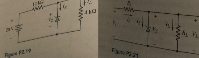
Question 1: In the voltage regulator circuit in Figure P2.21, V1 = 20 V, VZ = 10 V, Ri = 222Ω and Pz(max) = 400 mW. (a) Determine IL, Iz, and IL, if RL = 380Ω. (b) Determine the value of RL, that will establish Pz(max) in the diode. (c) Repeat part (b) if Ri = 175 Ω.

Question 2: A Zeiler diode is connected in a voltage regulator circuit as shown in Figure P2.21. The Zener voltage is Vz = 10 V and the Zener resistance is assumed to be rz = 0. (a) Determine the value of Ri such that the zener diode remains in breakdown if the load current varies from IL = 50 to diode remains in breakdown if the 500 mA and if the input voltage varies from VI = 15 to 20 V. Assume Iz (min) = 0.1/z(max). (b) Determine the power rating required for the Zener diode and the load resistor.

Question 3: Consider the Zener diode circuit in Figure 2.19 in the text. Assume parameter values of Vzo = 5.6 V (diode voltage when lz ≡ 0), rz = 3 Ω, = and Ri = 50Ω. Determine VL, Iz, IL, and the power dissipated in the diode for
(a) Vps = 10 V, RL = ∞; (b) Vps = 10V, RL = 200Ω; (c) Vps = 12 V, RL = ∞; and (d) VPs = 12 V, RL, = 200 Ω.

Question 4: Design a voltage regulator circuit such as shown in Figure P2.21 so that VL= 7.5 V. The Zener diode voltage is Vz = 7.5 V at Iz = 10 mA. The incremental diode resistance is rz = 12 Ω. The nominal supply voltage is Vi = 12 V and the nominal load resistance is RL = 1 kg2. (a) Determine R. (b) If V1 varies by ±10 percent, calculate the source regulation. What is the variation in output voltage? (c) If RL varies over the range of 1 kΩ < RL < ∞, what is the variation in output voltage? Determine the load regulation.

Question 5: A voltage regulator is to have a nominal output voltage of 10 V. The specified Zener diode has a rating of 1 W, has a 10 V drop at 1z = 25 mA, and has a Zener resistance of rz = 5Ω. The input power supply has a nominal value of Vps = 20 V and can vary by ±25 percent. The output load current is to vary between Iz = 5 mA and 20 mA. (a) If the minimum Zener current is to be 17 mA, determine the required R. (b) Determine the maximum variation in output voltage. (c) Determine the percent regulation.

2461_figure.jpg

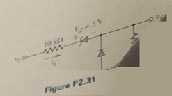
Question 6: Consider the circuit in Figure P2.31. Let Vy = 0. (a) Plot v0 versus vi over the range -10 ≤ vi ≤ + 10 V.(b) Plot i1, over the same input voltage range as part (a).

1162_figure1.jpg

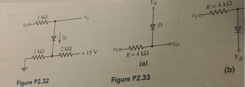
Question 7:  For the circuit in Figure P2.32. (a) plot vo versus 0 ≤ vi ≤ 15 v As some Vy = 0.7 V. Indicate all breakpoints. (b) Plot iD over the same range of input voltage. (c) Compare the results of parts (a) and (b) with a computer simulation.

Question 8: Each diode cut-in voltage is 0.7 V for the circuits shown in Figure P2.33. (a) Plot vo versus v1 over the range -5 ≤ v1 ≤ +5 V for the circuit in Figure P2.33(a) for (i) VB = 1.8 V and (ii) VB = -1.8 V. (b) Repeat part (a) for the circuit shown in Figure P2.33(b).

308_figure2.jpg

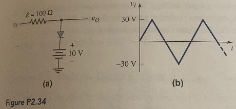
Question 9: The diode in the circuit of Figure P2.34(a) has piecewise linear parameters Vy = 0.7 V and rf =10 Ω (a) Plot vo versus vi for -30 ≤ v1 ≤ 30 V. (b) If the triangular wave, shown in Figure P2.34(b), is applied, plot the output versus time.

341_figure3.jpg

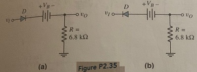
Question 10: Consider the circuits shown in Figure P2.35. Each diode cut-in voltage is Vy = 0.7 V. (a) Plot vo versus v1 over the range -10 ≤ v1 ≤ +10 V for the circuit in Figure P2.35(a) for (i) VB = 5 V and (ii) VB -5 V. (b) Repeat part (a) for the circuit in Figure P2.35(b).

2017_figure4.jpg

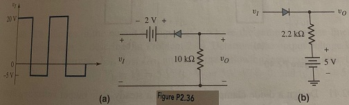
Question 11: Plot vo for each circuit in Figure P2.36 for the input shown. Assume (a) Vy = 0 and (b) Vy = 0.6 V.

33_figure5.jpg

Question 12: Consider the parallel clipper circuit in Figure 2.36 in the text. Assume Vz1 = 6 V, Vz, = 4 V, and Vy = 0.7 V for all diodes. For vI = 10 sin ωt, sketch vo versus time over two periods of the input signal.

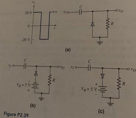
Question 13: Sketch the steady-state output voltage vo versus time for each circuit in Figure P2.39 with the input voltage given in Figure P2.39(a). Assume Vy = 0 and assume the RC time constant is large.

639_figure6.jpg

Electrical & Electronics, Engineering

  • Category:- Electrical & Electronics
  • Reference No.:- M93109223
  • Price:- $45

Priced at Now at $45, Verified Solution

Have any Question?


Related Questions in Electrical & Electronics

Nanotechnology engineering program assignment - passive

Nanotechnology Engineering Program Assignment - Passive Filters Q1) Determine what type of filter is in circuit shown. Calculate the cutoff frequency f c . Q2) Determine what type of filter is in circuit shown. Calculate ...

Research report1 read 3 to 4 journal articles about

Research report 1. Read 3 to 4 journal articles about digital control or industrial control, eg. one particular application, implementation aspect such as selection of sampling time, hardware etc. No text book example is ...

Nanotechnology engineering - resonance circuits questions

Nanotechnology Engineering - Resonance Circuits Questions - Q1) A series RLC network has R = 2KΩ, L = 40mH and C = 1μF. Calculate the impedance at resonance and at one-fourth, one-half, twice, and four times the resonant ...

Question -i a star-connected three-phase synchronous

Question - (i) A star-connected, three-phase synchronous induction motor takes a current of 10 amps from a 415 volt supply at unity power factor when supplying a steady load. If the synchronous reactance is 5 ohms/phase ...

Problem 1given a sequence xn for 0lenle3 where x0 1 x1 1

Problem # 1: Given a sequence x(n) for 0≤n≤3, where x(0) = 1, x(1) = 1, x(2) = -1, and x(3) = 0, compute its DFT X(k). (Use DFT formula, don't use MATLAB function) Problem # 2: Use inverse DFT and apply it on the Fourier ...

1 goalin this project you will solve a non-trivial design

1 Goal In this project you will solve a non-trivial design problem explicitly using the divide-and-conquer (D&C) approach. The main reason for using the D&C approach is the ease of the design process and the streamlined ...

Question 1 - for the transistor in the circuit shown in

Question 1 - For the transistor in the circuit shown in Figure, assume β = 120. Design the circuit such that I CQ = 0.15 mA and R TH = 200kΩ. What is the value of V CEQ ? Question 2 - (a) For the circuit shown in figure, ...

Questions -problem 1 - determine the laplace transform ofa

Questions - Problem 1 - Determine the Laplace transform of: (a) cos(ωt + θ) (b) sin(ωt + θ) Problem 2 - Obtain the Laplace transform of each of the following functions: (a) e -2t cos(3t)u(t) (b) e -2t sin(4t)u(t) (c) e - ...

1 a name the three major groups of contamination and

1. (a) Name the three major groups of contamination and briefly describe their physical characteristics. (b) Where do the above contamination types come from? Give one example of each. 2. Name two processes metrics which ...

Question 1 in the voltage regulator circuit in figure p221

Question 1: In the voltage regulator circuit in Figure P2.21, V 1 = 20 V, V Z = 10 V, R i = 222Ω and P z (max) = 400 mW. (a) Determine I L, I z , and I L , if R L = 380Ω. (b) Determine the value of R L , that will establ ...

  • 4,153,160 Questions Asked
  • 13,132 Experts
  • 2,558,936 Questions Answered

Ask Experts for help!!

Looking for Assignment Help?

Start excelling in your Courses, Get help with Assignment

Write us your full requirement for evaluation and you will receive response within 20 minutes turnaround time.

Ask Now Help with Problems, Get a Best Answer

Why might a bank avoid the use of interest rate swaps even

Why might a bank avoid the use of interest rate swaps, even when the institution is exposed to significant interest rate

Describe the difference between zero coupon bonds and

Describe the difference between zero coupon bonds and coupon bonds. Under what conditions will a coupon bond sell at a p

Compute the present value of an annuity of 880 per year

Compute the present value of an annuity of $ 880 per year for 16 years, given a discount rate of 6 percent per annum. As

Compute the present value of an 1150 payment made in ten

Compute the present value of an $1,150 payment made in ten years when the discount rate is 12 percent. (Do not round int

Compute the present value of an annuity of 699 per year

Compute the present value of an annuity of $ 699 per year for 19 years, given a discount rate of 6 percent per annum. As