The objective of this study is to develop a capacity to conduct the analytical studies sufficient to allow valid and responsible engineering decisions to be made in the context of system planning and operation. To do this we will study the behaviour of a simple (but representative) 17 bus power system, as illustrated in figure 1. The various capabilities of the Power World software will provide sufficient analysis tools for our purpose.
This project is to be conducted on an individual basis.
The study specification provided below is flexible and its intent is to expose students to a realistic system and to observe and interpret its behaviour, rather than simply obtain results for a prescribed set of scenarios. Each student may use a different approach to the factors studied.
1. Begin by entering your "Base Case" system as given into Power World. The Base Case represents the normal high load condition. Examine the power flows and the voltage profile of the network. All load buses should be within normal system tolerances (i.e. 0.95
p.u - 1.06 p.u.). Use caution when entering the tap-settings for the transformers.
2. Observe the system behaviour under the condition where any line or transformer is taken is out of service. This represents the N-1 contingency test. Are there any lines or transformers that can not be taken out of service without the system voltages departing from the acceptable limits (i.e. 0.95 p.u - 1.06 p.u.), or overloading of the remaining transformers and lines? In particular, are there sections of the network that are marginal? Power World has a Contingency function which may help. You can tabulate and summarise your results.
3. Define a light load case where the loads are about 40% of those shown. Power World has a Scale Case function which may be useful here. Are there any voltages that are unacceptably high or low (and why)? Suggest a remedial strategy to compensate for any voltages that are out of spec. and verify the effectiveness of the strategy (Note: this should not normally require any additional capital expenditure). Discuss the nature and source of problems associated with a lightly loaded system.
4. For the light load case repeat the N-1 contingency test. How does the system behaviour compare to the normal high load case? Maintenance schedules which require a transmission line or transformer to be taken out of service are often performed at times where the system is lightly loaded. What capacity does the system have to withstand another line or transformer tripping with one element already out of service for maintenance. This represents the N-2 contingency test.
5. If the system does not possess sufficient redundancy to tolerate the loss of any line or transformer, suggest a remedial course of action (this may include additional infrastructure), and verify the effectiveness of the approach. The anticipated load growth for the system is an additional 20% over the next ten years, distributed throughout the network. Can the modified system meet this new demand? Will the modified system be N-1 tolerant when the new load is placed on the system?
6. A new industrial client is to be connected to the system. The client has premises located in the vicinity of bus 7 (the distance to the client is approximately twice that between bus 7 and bus 8), and has an anticipated 32kV demand of 20MVA at 0.8pf lagging. Plan a connection for the new load with redundancy so that the client can still be supplied even if one line feeding it is lost. What effect will the new load have on the system performance? Can the system tolerate the loss of any line or transformer under the new conditions?
7. What is typical of real power loss in the system? Choose whatever case you wish, and see what happens to losses when fixed generation is altered. Move some generation away from bus 1 to bus 2, or add a generator at a bus elsewhere.
8. Return to the base case, and develop a PV and VQ curves for bus 15. Discuss potential voltage stability issues for this bus, and suggests ways to mitigate them.
9. Please note that there will be an additional task for the Project, based on the second Computer Lab session (in week 7). This task will be given to the students later. It is relatively small compared to the tasks 1...8.
Your project submission must consist of a report submitted electronically (via Turnitin). The report should be kept to 15 pages maximum, not including appendices. As you will generate large amounts of data in this study it is imperative that you devote time to the development of an effective way to present results. The report should describe the tasks and discuss the results. Compact data representation with the help of tables, figures and plots is appropriate in the body of the report. Large tables with data generated by PowerWorld should appear in Appendices. It is insufficient to simply provide 15 pages of simulation results. Correctness of the solutions, quality of discussion, quality of presentation, engineering judgement, use of the material studied in the course, and use of external material (for High Distinction mark range) will be assessed.
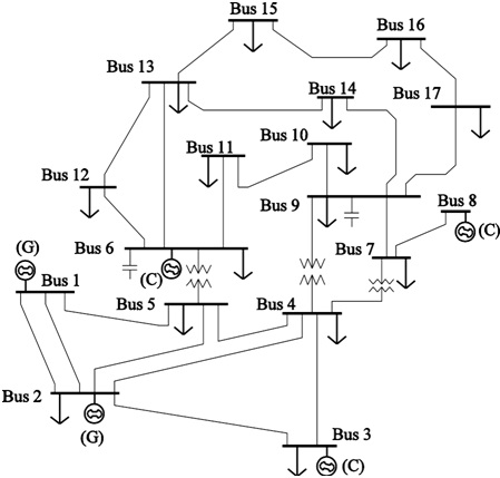
Figure Bus Power System
Attachment:- project.rar