Ask Question, Ask an Expert

+61-413 786 465

info@mywordsolution.com

Ask Electrical & Electronics Expert

Purpose

The aim of this experiment is to develop a bipolar transistor amplifier with a voltage gain of minus 25. The amplifier must accept input signals from a source impedance of 1 kW and provide an undistorted output amplitude of 5 V when driving a 560 W load. The bandwidth should extend from below 100 Hz to above 1 MHz.

Problems

1. Calculate the quiescent voltages VB, VE, and VC, and the currents IE and IC for the common emitter circuit in Figure 1. How much power is dissipated in the transistor itself? Is the power safely below Pmax?

2. Find the ac voltage gain of the circuit in Figure 1 for 10 kHz sine waves with the emitter bypass capacitor CE removed. Estimate the maximum amplitude of the output before clipping occurs. (The maximum output voltage is limited by the positive supply voltage, and the minimum is determined by the requirement that the collector voltage must be at least a few tenths of a volt above the emitter voltage.)

3. The emitter bypass capacitor can provide an AC ground path for the emitter, increasing the gain of the amplifier at high frequency. Considering the effects of the intrinsic emitter resistance re, what is the maximum possible AC voltage gain of the amplifier in Figure 1?

Will this gain likely be realized for 10 kHz sine waves? Why or why not?

4. What setting of the emitter trimpot is needed to give the required gain of -25? For the single stage in Figure 1, what are the input and output impedances rin and rout at 10 kHz and a gain of -25? (Note that rin is the impedance looking into the base in parallel with the base divider impedance.) Calculate the fraction of the original amplitude obtained when a 560 W load is connected to the output via a coupling capacitor.

5. Calculate the output impedance for the emitter follower circuit shown in Figure 2. What fraction of the original output amplitude do you expect to obtain when you attach the 560 W load to the emitter follower output?

1067_Develop a bipolar transistor amplifier with a voltage gain.png

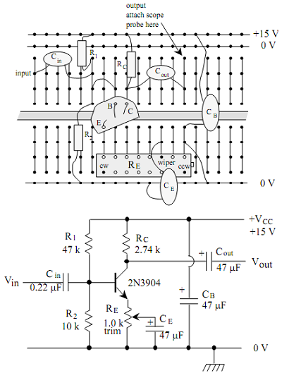
Figure1: Common Emitter Stage Layout and Schematic

1511_Develop a bipolar transistor amplifier with a voltage gain1.png

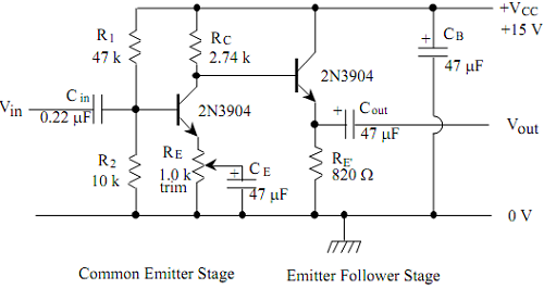
Figure 2: Complete Two-stage Amplifier Circuit

Outline of the Experiment

1 Verify that the 2N3904 is an NPN transistor using the digital multimeter. Is the 2N3906 a PNP or an NPN transistor?

2. Construct a common emitter transistor bias circuit. Confirm that the quiescent voltages are correct. Add coupling capacitors to the circuit to make an ac amplifier, and measure the ac voltage gain for 10 kHz sine waves. Verify that the gain has the expected value, and confirm that the output amplitude can reach 5 V before the extremes of the sine waves are clipped.

3. Make a variable gain amplifier by bypassing part of the emitter resistance with a capacitor. Find the maximum possible voltage gain and compare with your prediction.

4. Adjust the gain to the required value of -25. Find the effect on the output amplitude of placing a source impedance of 1 kW in series with the signal source. Also observe what happens when you place a 560 W load between the output and ground.

5. Now build an emitter follower stage as an impedance buffer between the amplifier and the load. Verify that the emitter follower alone has unit voltage gain. What happens now when you connect the load to the emitter follower output?

6. Test the performance of the complete circuit under the specified conditions: 1 kW source impedance and 560 W load. First reset the overall gain to -25 if it has changed. Check that the 5 V undistorted output amplitude is still available. Measure the gain versus frequency from 1 Hz to 10 Mhz.

Electrical & Electronics, Engineering

  • Category:- Electrical & Electronics
  • Reference No.:- M9307403

Have any Question?


Related Questions in Electrical & Electronics

Questions -problem 1 - given the sinuosidal voltage vt 50

Questions - Problem 1 - Given the sinuosidal voltage v(t) = 50 cos(30t+10 o ) V, find: (a) the amplitude V m (b) the period T, (c) the frequency f and (d) v(t) at t = 10 ms. Problem 2 - A current source in a linear circu ...

1 a name the three major groups of contamination and

1. (a) Name the three major groups of contamination and briefly describe their physical characteristics. (b) Where do the above contamination types come from? Give one example of each. 2. Name two processes metrics which ...

Case studythis assignment consists of a written report of

CASE STUDY This assignment consists of a written report of approximately 1000 words and any diagrams in which you are asked to critically compare different process methods used to achieve the same result and show an awar ...

Question 1 - for the transistor in the circuit shown in

Question 1 - For the transistor in the circuit shown in Figure, assume β = 120. Design the circuit such that I CQ = 0.15 mA and R TH = 200kΩ. What is the value of V CEQ ? Question 2 - (a) For the circuit shown in figure, ...

Question 1for the ce amplifier in figure 1 given the

Question 1 For the CE amplifier in Figure (1), given the following component parameters: Parameter Value β DC , β AC 150 V BE 0 . 7 V V CC 12 V R C 820 ? R E 1 100 ? R E 2 220 ? R 1 20 k? R 2 5 . 2 k? R L 100 k? C 1 , C ...

Research report1 read 3 to 4 journal articles about

Research report 1. Read 3 to 4 journal articles about digital control or industrial control, eg. one particular application, implementation aspect such as selection of sampling time, hardware etc. No text book example is ...

Summative assessmentin 2017 sej101 assessment will consist

Summative Assessment In 2017 SEJ101 assessment will consist of nine tasks that will develop a portfolio of your assessed work. Throughout the trimester you will have the opportunity for feedback on all nine tasks before ...

A four-pole star-connected squirrel-cage induction motor

A four-pole, star-connected, squirrel-cage induction motor operates from a variable voltage 50 Hz three-phase supply. The following results were obtained as the supply voltage was gradually reduced with the motor running ...

Advanced computational techniques in engineering assignment

Advanced Computational Techniques in Engineering Assignment - Optimisation For this assignment, you are required to carry out the process of attempting to solve different optimisation problems. For each question, you are ...

Questions -q1 a single-phase transformer rated 21 kv130 v

Questions - Q1. A single-phase transformer rated 2.1 kV/130 V, 7.8 kVA has the following winding parameters: r1= 0.7Ω, x1 = 0.9Ω, r2 = 0.04Ω and x2 = 0.05Ω. Determine: a. The combined winding resistance ________ Ω and le ...

  • 4,153,160 Questions Asked
  • 13,132 Experts
  • 2,558,936 Questions Answered

Ask Experts for help!!

Looking for Assignment Help?

Start excelling in your Courses, Get help with Assignment

Write us your full requirement for evaluation and you will receive response within 20 minutes turnaround time.

Ask Now Help with Problems, Get a Best Answer

Why might a bank avoid the use of interest rate swaps even

Why might a bank avoid the use of interest rate swaps, even when the institution is exposed to significant interest rate

Describe the difference between zero coupon bonds and

Describe the difference between zero coupon bonds and coupon bonds. Under what conditions will a coupon bond sell at a p

Compute the present value of an annuity of 880 per year

Compute the present value of an annuity of $ 880 per year for 16 years, given a discount rate of 6 percent per annum. As

Compute the present value of an 1150 payment made in ten

Compute the present value of an $1,150 payment made in ten years when the discount rate is 12 percent. (Do not round int

Compute the present value of an annuity of 699 per year

Compute the present value of an annuity of $ 699 per year for 19 years, given a discount rate of 6 percent per annum. As