Ask Question, Ask an Expert

+61-413 786 465

info@mywordsolution.com

Ask Electrical & Electronics Expert

Read the following instructions carefully.

1. This assignment forms part of the formal assessment for this module. If you fail to reach the required standard for the assignment then you will be allowed to resubmit but a resubmission will only be eligible for a Pass grade, not a Merit or Distinction.

You should therefore not submit the assignment until you are reasonably sure that you have completed it successfully. Seek your tutor's advice if unsure.

2. Ensure that you indicate the number of the question you are answering.

3. Make a copy of your answers before submitting the assignment.

4. Complete all details on the front page of this TMA and return it with the completed assignment including supporting calculations where appropriate.

Assessment Criteria

This assignment relates to the analysis, design and software emulation of linear and non-linear operational amplifier circuits. The assignment forms Element 1 of the module's assessment criteria that covers in part Learning Outcomes 3, 4 and 5 as indicated below.

MODULE LEARNING OUTCOMES

Knowledge and Understanding

1. Review and contrast actual characteristics of an operational amplifier with the ideal.
Cognitive and Intellectual Skills

2. Interpret manufacturers' data to match operational amplifier parameters to a given performance and application.
3. Analyse the performance of operational amplifier circuits in terms of gain, phase, stability and pulse response.
Practical and Professional Skills

4. Design, simulate, build and test operational amplifier circuits.
Key Transferable Skills

5. Apply mathematical skills in more complex contexts involving operational amplifiers.

1. FIGURE 1 shows two amplifier circuits, each of which has one unknown voltage (shown highlighted). Select, from TABLE A, the most appropriate value for the unknown voltages for each circuit. Assume that the op-amps are ideal and that the magnitude of their output voltages is less than their maximum peak output voltage swing (VOM).


-  1 mV


+


1 mV


-


1 V


+


1 V

-  2 mV

+

2 mV

-

2 V

+

2 V

-  3 mV

+

3 mV

-

3 V

+

3 V

-  4 mV

+

4 mV

-

4 V

+

4 V

-  5 mV

+

5 mV

-

5 V

+

5 V

-  6 mV

+

6 mV

-

6 V

+

6 V

-  7 mV

+

7 mV

-

7 V

+

7 V

-  8 mV

+

8 mV

-

8 V

+

8 V

-  9 mV

+

9 mV

-

9 V

+

9 V

-  10 mV

+

10 mV

-

10 V

+

10 V

-  100 mV

+

100 mV

-

100 V

+

100 V

-  500 mV

+

500 mV

-

300 V

+

300 V

TABLE A

2. A 12-bit DAC (Digital to Analogue Converter) gives an output range of 0 to -1 mA for a digital input word of 0 to 4095. The required output, however, is for a bipolar voltage range of ± 5 V.

(a) Design a current-to-voltage converter circuit to achieve the required bipolar output voltage.

(b) Test your design on PSpice and produce suitable graphical output to demonstrate the circuit's operation.

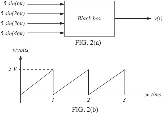
3. FIGURE 2(a) shows a ‘black box' that is to partially synthesise a ‘saw- tooth' waveform of FIGURE 2(b) by using the Fourier series algorithm:

v(t) = 2/Π(sin(ωt) + 1/2sin(2ωt) + 1/3sin(ωt) + 1/4sin(4ωt) +.....)

(a) Design an operational amplifier circuit to perform the function of the ‘black box'.

(b) Test your design on PSpice and produce a graph of the output waveform.

2256_figure1.jpg

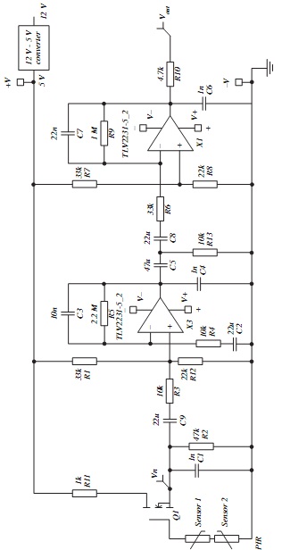
4. FIGURE 3 (on page 7) shows a PIR (passive infra-red) detector and its associated amplifier, as used in burglar alarm systems.

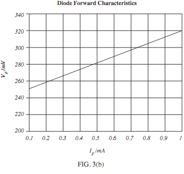
(a) The detector is powered from a 12 V unregulated supply that needs to be stepped down to 5 V. Design a suitable 12-to-5 V voltage converter using an op-amp and a diode that has the forward characteristics given in FIGURE 3(b).

(b) Estimate the quiescent voltages at the inputs and outputs of the two op-amps and the overall voltage gain (in decibels) of the circuit at the frequency of operation. State any assumptions made.

65_figure2.jpg

1280_figure3.jpg

Electrical & Electronics, Engineering

  • Category:- Electrical & Electronics
  • Reference No.:- M92304916
  • Price:- $45

Priced at Now at $45, Verified Solution

Have any Question?


Related Questions in Electrical & Electronics

Questions -problem 1 - a series rlc network has r 2 komega

Questions - Problem 1 - A series RLC network has R = 2 kΩ, L = 40 mH and C = 1μF. Calculate the impedance at resonance and at one-fourth, one-half, twice, and four times the resonant frequency. Problem 2 - Design a serie ...

Case studythis assignment consists of a written report of

CASE STUDY This assignment consists of a written report of approximately 1000 words and any diagrams in which you are asked to critically compare different process methods used to achieve the same result and show an awar ...

1 a name the three major groups of contamination and

1. (a) Name the three major groups of contamination and briefly describe their physical characteristics. (b) Where do the above contamination types come from? Give one example of each. 2. Name two processes metrics which ...

Problem 1given a sequence xn for 0lenle3 where x0 1 x1 1

Problem # 1: Given a sequence x(n) for 0≤n≤3, where x(0) = 1, x(1) = 1, x(2) = -1, and x(3) = 0, compute its DFT X(k). (Use DFT formula, don't use MATLAB function) Problem # 2: Use inverse DFT and apply it on the Fourier ...

1 goalin this project you will solve a non-trivial design

1 Goal In this project you will solve a non-trivial design problem explicitly using the divide-and-conquer (D&C) approach. The main reason for using the D&C approach is the ease of the design process and the streamlined ...

Assignment - power distribution system transformerscomplete

Assignment - Power Distribution System Transformers Complete your calculations, drawings, and answers, neatly handwritten on these sheets and hand in at the start of lecture in week 6. Absolutely no late submissions will ...

Problems -problem 1 - find v0 in the op amp circuit of fig

Problems - Problem 1 - Find v 0 in the op amp circuit of Fig. 1. Problem 2 - Compute i 0 (t) in the op amp circuit in Fig. 2 if v s = 4 cos(10 4 t). Problem 3 - If the input impedance is defined as Z in = v s /I s , find ...

Electrical engineering questions -q1 two ideal voltage

Electrical Engineering Questions - Q1. Two ideal voltage sources designated as machines 1 and 2 are connected, as shown in the figure below. Given E 1 = 65∠0 o V, E 2 = 65∠30 o V, Z = 3Ω. Determine if Machine 1 is genera ...

1 a name the three major groups of contamination and

1. (a) Name the three major groups of contamination and briefly describe their physical characteristics. (b) Where do the above contamination types come from? Give one example of each. 2. Name two processes metrics which ...

Nanotechnology engineering - resonance circuits questions

Nanotechnology Engineering - Resonance Circuits Questions - Q1) A series RLC network has R = 2KΩ, L = 40mH and C = 1μF. Calculate the impedance at resonance and at one-fourth, one-half, twice, and four times the resonant ...

  • 4,153,160 Questions Asked
  • 13,132 Experts
  • 2,558,936 Questions Answered

Ask Experts for help!!

Looking for Assignment Help?

Start excelling in your Courses, Get help with Assignment

Write us your full requirement for evaluation and you will receive response within 20 minutes turnaround time.

Ask Now Help with Problems, Get a Best Answer

Why might a bank avoid the use of interest rate swaps even

Why might a bank avoid the use of interest rate swaps, even when the institution is exposed to significant interest rate

Describe the difference between zero coupon bonds and

Describe the difference between zero coupon bonds and coupon bonds. Under what conditions will a coupon bond sell at a p

Compute the present value of an annuity of 880 per year

Compute the present value of an annuity of $ 880 per year for 16 years, given a discount rate of 6 percent per annum. As

Compute the present value of an 1150 payment made in ten

Compute the present value of an $1,150 payment made in ten years when the discount rate is 12 percent. (Do not round int

Compute the present value of an annuity of 699 per year

Compute the present value of an annuity of $ 699 per year for 19 years, given a discount rate of 6 percent per annum. As