Ask Electrical & Electronics Expert

Part A -

Problem 1 -

Compute the following convolutions - Since we have unit step functions available to express functions that are 0 for t < 0, you should be able to easily express your answers for parts (a) and (b) a single line, without a giant "conditional statement". Part (c) has three regions; you should still be able to express your answer in one line by employing a difference of unit step functions.

(a) exp(-2t)u(t) * exp(-4t)u(t)

(b) exp(-2t)u(t) * exp(-2t)u(t)

(c) [u(t) - u(t-2π)] sin(t)u(t)

Problem 2 -

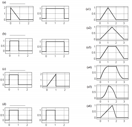
For each pair of signals on the left, select the signal on the right that is the convolution of the two signals. Not all of the signals on the right will be used, and some may be used more than once.

722_figure.png

Part B -

Problem 1 -

Now that you're getting the hang on an amazing property of transmission lines with sinusoidal signals, we will explore another method of matching called series-stub matching. Consider the below diagram. A 40 Ω transmission line must be matched to an antenna. The antenna is characterized by a 50 Ω resistor in series with a 10/(3π) pF capacitor. The antenna is connected to a feeder transmission line that has impedance of 100 Ω and is exactly one-quarter wavelength long. To match that antenna and feeder line to the 40 Ω power transmission line and eliminate reflections, you connect a series transmission line at the end of the quarter-wave segment. This stub is shorted at the end.

2446_figure1.png

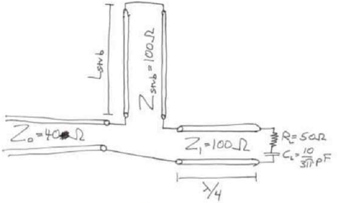
a. What is the smallest length Lstub that produces a perfect match, meaning that any voltage from the generator (the generator is off the left edge of the diagram) does not return to the generator? Your answer should be as a fraction of a wavelength.

b. You designed this circuit for a 3 GHz wi-fi transceiver. What is the voltage standing wave ratio at 3 GHz on the input section of the transmission line (that's the section leading to the generator)?

c. The circuit has been built and is sitting on your lab bench. But your annoying professor just decided to switch to a different frequency, and wants to try out 2 GHz. Since you've taken 3025 and remember a really fun homework assignment, you know that series-stud matching only works at one frequency, so you need to calculate how well it will match at this new frequency. What is the VSWR if you use the same circuit board you've built, but inject 2 GHz instead?

d. This is not part of the homework, but some food for thought: What do you think determines the "bandwidth", i.e. how quickly or slowly the quality of the match falls off as you move away from 3 GHz? Can you think of any ways to either increase or decrease the bandwidth?

Problem 2 -

So you build the circuit in part 1(b). But everything in your design assumed that the transmission line would be lossless. But you've taken 3025 and remember a really fun homework assignment, so you know that board fabrication is never precisely what you designed, anyways. So you decide to take some high frequency measurements and find the following transmission line parameters at 3 GHL: L = 10.1 nH/cm, C = 1.1 pF/cm

a. What is the characteristic impedance?

b. You then realize that you should also measure the losses, too. So with additional high frequency measurements, you calculate that G = 0.014 5/cm, R = 143.5 Ω /cm. What is the characteristic impedance including the losses?

c. What is the propagation constant y?

d. For a transmission line 10 cm long, how much will a 1 V signal attenuate?

Electrical & Electronics, Engineering

  • Category:- Electrical & Electronics
  • Reference No.:- M92476210

Have any Question?


Related Questions in Electrical & Electronics

Question 1for the ce amplifier in figure 1 given the

Question 1 For the CE amplifier in Figure (1), given the following component parameters: Parameter Value β DC , β AC 150 V BE 0 . 7 V V CC 12 V R C 820 ? R E 1 100 ? R E 2 220 ? R 1 20 k? R 2 5 . 2 k? R L 100 k? C 1 , C ...

Question -i a star-connected three-phase synchronous

Question - (i) A star-connected, three-phase synchronous induction motor takes a current of 10 amps from a 415 volt supply at unity power factor when supplying a steady load. If the synchronous reactance is 5 ohms/phase ...

1 a name the three major groups of contamination and

1. (a) Name the three major groups of contamination and briefly describe their physical characteristics. (b) Where do the above contamination types come from? Give one example of each. 2. Name two processes metrics which ...

Question 1 in the voltage regulator circuit in figure p221

Question 1: In the voltage regulator circuit in Figure P2.21, V 1 = 20 V, V Z = 10 V, R i = 222Ω and P z (max) = 400 mW. (a) Determine I L, I z , and I L , if R L = 380Ω. (b) Determine the value of R L , that will establ ...

Summative assessmentin 2017 sej101 assessment will consist

Summative Assessment In 2017 SEJ101 assessment will consist of nine tasks that will develop a portfolio of your assessed work. Throughout the trimester you will have the opportunity for feedback on all nine tasks before ...

1 a name the three major groups of contamination and

1. (a) Name the three major groups of contamination and briefly describe their physical characteristics. (b) Where do the above contamination types come from? Give one example of each. 2. Name two processes metrics which ...

1 a name the three major groups of contamination and

1. (a) Name the three major groups of contamination and briefly describe their physical characteristics. (b) Where do the above contamination types come from? Give one example of each. 2. Name two processes metrics which ...

Case studythis assignment consists of a written report of

CASE STUDY This assignment consists of a written report of approximately 1000 words and any diagrams in which you are asked to critically compare different process methods used to achieve the same result and show an awar ...

Problem 1 a two-phase servomotor has rated voltage applied

Problem 1: A two-phase servomotor has rated voltage applied to its excitation winding. The torque speed characteristic of the motor with Vc = 220 V, 60 Hz applied to its control phase winding is shown in Fig.1. The momen ...

Electrical engineering questions -q1 two ideal voltage

Electrical Engineering Questions - Q1. Two ideal voltage sources designated as machines 1 and 2 are connected, as shown in the figure below. Given E 1 = 65∠0 o V, E 2 = 65∠30 o V, Z = 3Ω. Determine if Machine 1 is genera ...

  • 4,153,160 Questions Asked
  • 13,132 Experts
  • 2,558,936 Questions Answered

Ask Experts for help!!

Looking for Assignment Help?

Start excelling in your Courses, Get help with Assignment

Write us your full requirement for evaluation and you will receive response within 20 minutes turnaround time.

Ask Now Help with Problems, Get a Best Answer

Why might a bank avoid the use of interest rate swaps even

Why might a bank avoid the use of interest rate swaps, even when the institution is exposed to significant interest rate

Describe the difference between zero coupon bonds and

Describe the difference between zero coupon bonds and coupon bonds. Under what conditions will a coupon bond sell at a p

Compute the present value of an annuity of 880 per year

Compute the present value of an annuity of $ 880 per year for 16 years, given a discount rate of 6 percent per annum. As

Compute the present value of an 1150 payment made in ten

Compute the present value of an $1,150 payment made in ten years when the discount rate is 12 percent. (Do not round int

Compute the present value of an annuity of 699 per year

Compute the present value of an annuity of $ 699 per year for 19 years, given a discount rate of 6 percent per annum. As