Lab 2 Procedures
Part I - Design a Multiplier
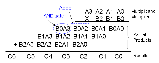
In the part of the lab, you are required to design a multiplier, which does the multiplication of a 3-bit number B(2:0) by a 4-bit number A(3:0).
The multiplication process can be illustrated as follows:

You are required to use half adders, full adders and AND gates to implement this multiplier.
- Design: draw out the logic diagram of the multiplier (e.g. see the logic diagram of a 2-bit and 2-bit multiplier illustrated in the Pre-lab and Background Information). Remember, you may only use half adders, full adders and AND gates. You will need to include this logic diagram in your lab report.
- Create a new design file "YourFirstNameLastNameLab2Part1" under your default design directory/folder. In this design file, draw the circuit you have designed from step 1. You may use SPDT switches to provide the multiplicand and multiplier inputs. You may also use LED arrays to demonstrate your resulting binary number of the multiplier (each LED can be used for a single bit in the multiplier result).
- Run simulations to test your design. You should test a few possible pairs of the numbers A and B, e.g. multiply the decimal equivalents: 8x2, 11x3, etc. You should verify that the results generated (as indicated in the LED lights if you choose to use the LED lights to demonstrate your multiplication results) are correct for each of the number pairs. Capture a screenshot for each of the A & B number pairs you tested and include an explanation on how you can conclude that your circuit is functioning correctly.
- Once you have verified your design logically in step 3, use your multiplier to conduct the following multiplications, use a table to list your inputs and expected outputs. Capture a screen shot for each of the following multiplications and include an explanation on how you verify that your circuit does the multiplications correctly for the following cases.
- 5x3
- 15x5
- 9x7
- 15x7
Part II - Design a Synchronous Counter
Design a synchronous counter to produce the following binary sequence. Use J-K flip-flops and other gates necessary:
1 - 4 - 3 - 5 - 7 - 6 - 2 - 1 - 4 - .......
- Design: draft the specification for the counter including the inputs and outputs. Construct state tables based on your specification, and use the K-map if necessary to optimize your functions for the outputs. Include the specification, input/output definitions, state tables, and the K-maps in your lab report.
- Create a new design file "YourFirstNameLastNameLab2Part2" under your default design directory/folder. In this design file, draw the circuit you have designed from step 1. You may use SPDT switches to provide control inputs. You may use LED arrays to show your binary sequence or use a 7-segment display to display the binary sequence in a human readable manner.
- Run simulations to test your design. You should verify that the counter you design generates the correct sequence. Capture a series of screenshots to demonstrate the correct sequence generated by your counter and include a short explanation on how you can conclude that your circuit is functioning correctly.
Part III - Design a Shift Register
A Shift Register is a series of flip-flops connected so that data can be transferred to a neighbor each time the clock pulse is active. These shift registers can be constructed using D or J-K flip-flops.
A shift register counter is a shift register with the serial output connected back to the serial input to produce special sequences. Two of the most common shift register counters are the Johnson Counter [Twisted Ring Counter] and the Ring Counter [Overbeck Counter].
- Conduct research on what Ring Counter and Johnson Counter are and what their expected functions are. Include your research results in your lab report.
- Build a 5-bit Ring Counter using J-K flop-flops, and again using D flip-flops. Include the state tables and confirm that each produces five states.
- Build a 5-stage Johnson Counter using J-K flip-flops, and again using D flip-flops. Include the state tables and confirm that each produces ten states.
- Create a new design file "YourFirstNameLastNameLab2Part3" under your default design directory/folder. In this design file, draw the circuit for all the four counters you have designed from step 1 and step 2. Apply the same clock source to all the four counters and use different LED arrays to demonstrate the outputs of each counter.
- Run simulations to test your design. You run through all the possible states for your Ring Counters as well as your Johnson Counters. Capture a series of screenshots to show all the states of your counters in the correct sequence and include an explanation on how you can conclude that your counters are all functioning correctly.