In submitting the problem set, provide a title page with the required information. This is followed by numbered pages showing the results for the four problems. For each of the four problems, two figures will be present. The first figure is the developed MATLAB script file (be sure to use all black text and a fixed width font like Courier) while the second figure shows the graphical results. For each figure, provide a numbered descriptive figure caption while for the m file provide appropriate comments; in the very least, the first line of code must contain a comment line with your name, course number and semester/year. For a low pass or high pass filter, mark the critical frequency on the amplitude/magnitude plot while for a band pass or band reject filter mark the resonant (center) frequency on the amplitude/magnitude plot. (For a low/high pass filter, the critical frequency has a gain that is 3dB less than the maximum gain. For a band pass/reject filter, the resonant/center frequency occurs at the maximum or minimum gain respectively.) If necessary, move the resulting box marker so it covers the least amount of important information on the graph. ]
Note that by default, the horizontal axis for the bode command in MATLAB generates a horizontal axis in rad/sec (ω). one must have a horizontal axis in Hz (f). As such, for each filter, have the command
set(cstprefs.tbxprefs,'FrequencyUnits','Hz') just before the bode command in the m file.
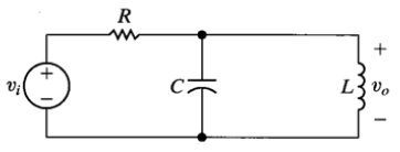
problem) The transfer function for the frequency selective circuit in Figure 1 can be shown to be
Vo(s)/Vi(s) = [(-R2/R1)/ sR2C+1]
where R1=1.5kΩ, R2= 1.5kΩ and C= 0.2µF. Use MATLAB to obtain the amplitude and phase frequency response using the tf and bode commands. Show the m file used and the resulting plot. The plot must have the title “Bode plot for problem 1 by Jane Doe”. Here, Jane Doe is replaced by your name. For the Bode plot figure caption, indicate the filter type (low pass, high pass, band pass or band reject) and critical frequency (if low pass or high pass) or resonant (center) frequency (if band pass or band reject) in Hz.
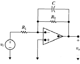
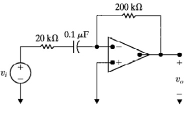
problem) The transfer function for the frequency selective circuit in Figure can be shown to be
Vo(s)/Vi(s) = [-sR2C/ sR1C+1]
where R1= 20kΩ, R2= 200kΩ and C= 0.1µF. Use MATLAB to obtain the amplitude and phase frequency response using the tf and bode commands. Show the m file used and the resulting plot. The plot must have the title “Bode plot for problem 2 by Jane Doe”. Here, Jane Doe is replaced by your name. For the Bode plot figure caption, indicate the filter type (low pass, high pass, band pass or band reject) and critical frequency (if low pass or high pass) or resonant (center) frequency (if band pass or band reject) in Hz. That is, configure MATLAB so that the horizontal axis is Hz and not the default rad/s (the frequency range will be determined automatically by MATLAB).
problem) The transfer function for the frequency selective circuit in Figure which is shown below can be represented as:
Vo(s)/Vi(s) = [s2RLC+R/ s2RLC+sL+R]
shown to be where R=2.2kΩ, L= 560µH and c= 5nF. Use MATLAB to obtain the amplitude and phase frequency response using the tf and bode commands. Show the m file used and the resulting plot. The plot must have the title “Bode plot for problem 3 by Jane Doe”. Here, Jane Doe is replaced by your name. For the Bode plot figure caption, indicate the filter type (low pass, high pass, band pass or band reject) and critical frequency (if low pass or high pass) or resonant (center) frequency (if band pass or band reject) in Hz. That is, configure MATLAB so that the horizontal axis is Hz and not the default rad/s (the frequency range will be determined automatically by MATLAB).
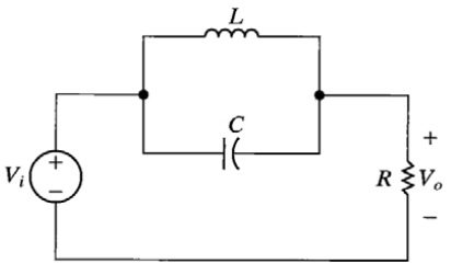
problem) The transfer function for the frequency selective circuit in Figure which is shown below can be represented as:
Vo(s)/Vi(s) = [sL/ s2RLC+sL+R]
Where R=2.2kΩ, L= 560µH and c= 5nF. Use MATLAB to obtain the amplitude and phase frequency response using the tf and bode commands. Show the m file used and the resulting plot. The plot must have the title “Bode plot for problem 4 by Jane Doe”. Here, Jane Doe is replaced by your name. For the Bode plot figure caption, indicate the filter type (low pass, high pass, band pass or band reject) and critical frequency (if low pass or high pass) or resonant (center) frequency (if band pass or band reject) in Hz. That is, configure MATLAB so that the horizontal axis is Hz and not the default rad/s (the frequency range will be determined automatically by MATLAB)