Ask Question, Ask an Expert

+61-413 786 465

info@mywordsolution.com

Ask Mechanical Engineering Expert

Dynamics and Control Project - Modelling of a 2 DOF System, Vibration Analysis and Experimental Verification

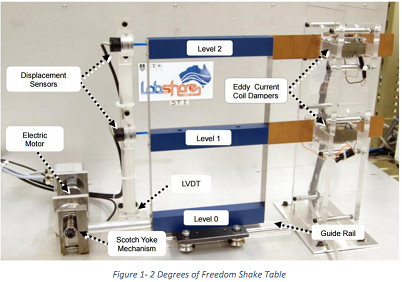
The Shake Table rig (Figure 1) was designed to model the behaviour of a building during an earthquake scenario. The rigs have been developed as two-storey structures that emulate vibrations in a single direction with 2 degrees of freedom. The rigs were designed to help students to break down and understand the complex dynamics of such a system.

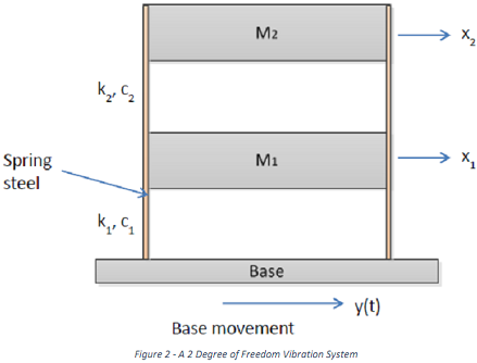
Students will model the 2 DOF system (using the simplified diagram in Figure 2), perform a vibration analysis and verify the results experimentally both in MATLAB and using the remote lab rigs.

You are required to read the document "Shake_Table_User_Guide_V2-1.pdf" for detailed information about the shake table rigs. Variance data on each of the rigs can be found in "Shake_Table_Variance_Data_2014-08-20.pdf".

1789_Figure.png

Students are required to produce a report detailing the three parts to the project, along with an insightful discussion and reflection relating to the tasks completed.

Part 1: Modelling of a 2DOF System

1. Draw the free body diagrams for the two masses in the system based on the simplified diagram in Figure 2.  

2. Derive the differential equations of motion for the system. The displacements x1(t) of M1 and x2(t) of x2 are measured from the rest positions of the masses.

Figure 2 shows a shear building with base motion. This building is modelled as a 2 DOF dynamic system where:

M1 = M2 = M = 1.178 kg

k1 = k2 = k = 370.374

C1 = C2 = C = 0.05 N.S/m

y(t) =  y0 sin(ωt)

Where k and c are the total values of stiffness and damping for each of the levels of the structure.

1421_Figure1.png

Part 2: Vibration Analysis

1. By assuming un-damped free vibration, calculate the natural frequencies of the system: ω1 and ω2.

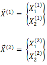
2.  Calculate the normal modes of vibration corresponding to ω1 and ω2, and draw their modal shapes:

1280_Figure2.png

3. Obtain the transfer functions for each of the masses, based on the differential equations of motion from Part 1 (Damped, Forced Vibration):

X1(S)/Y(S)

X2(S)/Y(S)

4. Using MATLAB/Simulink, analyse the responses x1(t) and x2(t) due to the following inputs:

Unit step base movement:       y(t) = 1

Harmonic motion of the base: y(t) = 0.7 sin(ω1t)

Harmonic motion of the base: y(t) = 0.7 sin(ω2t)

Part 3: Experimental Verification

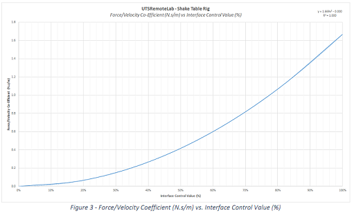
Record and plot the actual responses (i.e. produce two graphs) from the UTS remote vibration (Shaker Table) laboratory by setting the frequencies of the base movement to  f1 = ω1/2π and f2 = ω2/2π. Students should set the total system damping (% on the remote lab interface, given C1 = C2 = 0.05) using the information below.

Note: The relationship between the damping interface control value  (%)  and damping coefficient (N.s/m) is shown in Figure 3 and is given by the following equation:

y = 1.669x2

1905_Figure3.png

Provide an insightful, clear, relevant but brief discussion and reflection on the tasks performed in this report. Draw some conclusions about why modelling such a system might be useful in real life engineering practice. Also discuss how the simulated results compare with the real life experimental (shaker table) results.

Attachment:- Assignment Readings.rar

Mechanical Engineering, Engineering

  • Category:- Mechanical Engineering
  • Reference No.:- M92278126

Have any Question?


Related Questions in Mechanical Engineering

Problem -a long pipe od 1413 mm id 1318 mm kp 20 wmk

Problem - A long pipe (OD = 141.3 mm, ID =131.8 mm, k p = 20 W/m.K) supplies hot pressurized liquid water at 400 K to a heater in a factory. The pipe has an insulation thickness of 100 mm. A new efficient heater replaces ...

Problem on shaft -assuming no frictional losses a torque of

Problem on Shaft - Assuming no frictional losses, a torque of T = 750lb·in is applied through the shaft of gear F in order to drive the roller chain at point B at a constant speed. The chain sprocket has a pitch diameter ...

The aim of the project is to demonstrate certain aspects of

The aim of the project is to demonstrate certain aspects of engineering materials in different applications. The projects will be assessed on the basis of a written Research Report. The report should clearly show what yo ...

Fluid mechanics assignment - viscous flow in pipesq1 as

Fluid Mechanics Assignment - Viscous Flow in Pipes Q1. As shown in the figure below, water "bubbles up" 3 in. above the exit of the vertical pipe attached to three horizontal pipe segments. The total length of the 0.75-i ...

Materials behaviour from atoms to bridges assignment -

Materials Behaviour from Atoms to Bridges Assignment - Distributed loads and static equilibrium (Please note: you should show your steps with necessary figures) Q1. Two beam sections are jointed at C and supported at A b ...

Mechanical engineering assignment task - solve the given

Mechanical Engineering Assignment Task - Solve the given problem. Task 1 - A spring with a one-turn loop of 40mm mean radius is formed from a round section of wire having 5 mm diameter. The straight tangential legs of th ...

5star questions amp answers1a define heat treatment bname

5 STAR QUESTIONS & Answers 1. A) Define Heat treatment B) Name different types of heat treatment processes C) Write any 4 purposes of Heat treatment 2. Explain various Heat treatment processes 3. A) Compare Thermo plasti ...

Fluid mechanics assignment - finite control volume analysis

Fluid Mechanics Assignment - Finite Control Volume Analysis and Dimensional Analysis Q1. The wind blows through a 7ft × 10ft garage door opening with a speed of 5 ft/s as shown in the figure. Determine the average speed, ...

Structural mechanics questions -q1 a 150-lb bucket is

Structural Mechanics Questions - Q1. A 150-lb bucket is suspended from a cable on the wooden frame. Determine the resultant internal loadings on the cross section at D, and at E. Q2. The shaft is supported at its ends by ...

Question - truss structureconsider the three membered

Question - Truss Structure Consider the three membered planar truss structure shown in the figure below. All members of the truss have identical square cross-sectional area (A) of 25 mm x 25 mm, and Youngs Modulus (E) = ...

  • 4,153,160 Questions Asked
  • 13,132 Experts
  • 2,558,936 Questions Answered

Ask Experts for help!!

Looking for Assignment Help?

Start excelling in your Courses, Get help with Assignment

Write us your full requirement for evaluation and you will receive response within 20 minutes turnaround time.

Ask Now Help with Problems, Get a Best Answer

Why might a bank avoid the use of interest rate swaps even

Why might a bank avoid the use of interest rate swaps, even when the institution is exposed to significant interest rate

Describe the difference between zero coupon bonds and

Describe the difference between zero coupon bonds and coupon bonds. Under what conditions will a coupon bond sell at a p

Compute the present value of an annuity of 880 per year

Compute the present value of an annuity of $ 880 per year for 16 years, given a discount rate of 6 percent per annum. As

Compute the present value of an 1150 payment made in ten

Compute the present value of an $1,150 payment made in ten years when the discount rate is 12 percent. (Do not round int

Compute the present value of an annuity of 699 per year

Compute the present value of an annuity of $ 699 per year for 19 years, given a discount rate of 6 percent per annum. As