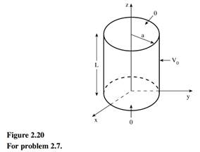
Research report 1. Read 3 to 4 journal articles about digital control or industrial control, eg. one particular application, implementation aspect such as selection of sampling time, hardware etc. No text book example is ...
|
Assignment - Problem 1 - a) Consider the simplified dc system shown in Fig. 1. Only one converter is modeled, with the remote end represented by a dc source. The ac system is rated at 345 kV, with the converter transform ...
|
Research report 1. Read 3 to 4 journal articles about digital control or industrial control, eg. one particular application, implementation aspect such as selection of sampling time, hardware etc. No text book example is ...
|
Summative Assessment In 2017 SEJ101 assessment will consist of nine tasks that will develop a portfolio of your assessed work. Throughout the trimester you will have the opportunity for feedback on all nine tasks before ...
|
A four-pole, star-connected, squirrel-cage induction motor operates from a variable voltage 50 Hz three-phase supply. The following results were obtained as the supply voltage was gradually reduced with the motor running ...
|
Question 1 - For the transistor in the circuit shown in Figure, assume β = 120. Design the circuit such that I CQ = 0.15 mA and R TH = 200kΩ. What is the value of V CEQ ? Question 2 - (a) For the circuit shown in figure, ...
|
Assignment - Power Distribution System Transformers Complete your calculations, drawings, and answers, neatly handwritten on these sheets and hand in at the start of lecture in week 6. Absolutely no late submissions will ...
|
Question 1. A pnp transistor with β = 60 is connected in a common-base configuration as shown in figure P5.8 (a) The emitter is driven by a constant-current source with I E = 0.75 mA. Determine I B , I C , α, and V C . ( ...
|
Electrical Engineering Questions - Q1. Two ideal voltage sources designated as machines 1 and 2 are connected, as shown in the figure below. Given E 1 = 65∠0 o V, E 2 = 65∠30 o V, Z = 3Ω. Determine if Machine 1 is genera ...
|
Question 1: In the voltage regulator circuit in Figure P2.21, V 1 = 20 V, V Z = 10 V, R i = 222Ω and P z (max) = 400 mW. (a) Determine I L, I z , and I L , if R L = 380Ω. (b) Determine the value of R L , that will establ ...
|
|