Ask Electrical & Electronics Expert

Part-1

Q1: Illustrate the radio frequency system of an amplitude modulated transmitter using block diagram. Explain the function of each stage of the transmitter and how is this related to stages connected at the input and output of each stage.

Q2: Using block diagram illustrate an AM modulator explaining the function of each block. Using Multisim or any other relevant software:

a. Produce an AM signal with the following parameters:

Carrier frequency:                                 fc = 100kHz

Message frequency:                              fm= 800Hz

Modulation index:                                       m=1

b. Detect and reproduce (demodulate) the message signal. Measure the frequency of the detected signal and compare that with the frequency of the message.

Provide screenshots for modulated and demodulated signals with their relevant information

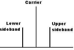
Q3: Figure 1 shows the spectrum of a double sideband full carrier (DSBFC).Calculate the frequencies of the DSBFC spectrum. Suggest a method and present your calculation to detect the lower side band at the output. This should produce a single sideband frequency spectrum knowing that the parameters of the spectrum are:

Carrier frequency:                                  fc = 10kHz

Message frequency:                              fm= 150Hz

1098_Frequency-modulated transmitter.png

Part-2

Derive a system diagram for a frequency-modulated transmitter and explain the function of each stage

Analyse angle modulation

Q1:Illustrate the radio frequency system of a frequency modulated transmitter using block diagram. Explain the function of each stage of the transmitter and how is this related to the stages connected at the input and output of each stage.

Q2: For the following parameters, use Multisim or any relevant software to:

a.    Produce an FM modulated signal:

Carrier frequency:                                   fc = 5kHz

Message frequency:                              fm= 500Hz

Modulation index:                                        ?=5

b. Analyse the effect of changing the modulation index to ?=2 and ?=8. Discuss the changes resulted in the FM output

Task 3

Draw a block diagram of an AM tuned-radio frequency (TRF) receiver and explain its operation

Tuned Radio Receivers are of the oldest receivers that were used until World War 2. Draw a block diagram for a TRF radio and give an explanation to the function of each stage an the operation of the complete TRF radio.

Task 4

Explain the principle of operation of the superheterodyne receiver

Superheterodyne receiver, that sometimes called superhet, uses frequency mixing principles to convert the received radio frequency signal to a fixed intermediate frequency (IF). Electronically, the new IF signal can easily be processed than the received radio carrier frequency. Using a block diagram, explain the principle of operation of the superheterodyne receiver and the function of each stage.

Task 5

Explain the necessary arrangements for transceiver operation

Having a transmitter and receiver working separately such as radio station (only transmitter) and home radios (only receiver) is not difficult. Difficulties arises when both transmitter and receiver are joined in one circuit board to obtain a transceiver that transmit and receive signals. Explain the necessary arrangement needed to overcome these difficulties and for the transceiver to operate safely.

Electrical & Electronics, Engineering

  • Category:- Electrical & Electronics
  • Reference No.:- M9457541
  • Price:- $70

Priced at Now at $70, Verified Solution

Have any Question?


Related Questions in Electrical & Electronics

Question 1for the ce amplifier in figure 1 given the

Question 1 For the CE amplifier in Figure (1), given the following component parameters: Parameter Value β DC , β AC 150 V BE 0 . 7 V V CC 12 V R C 820 ? R E 1 100 ? R E 2 220 ? R 1 20 k? R 2 5 . 2 k? R L 100 k? C 1 , C ...

Question -i a star-connected three-phase synchronous

Question - (i) A star-connected, three-phase synchronous induction motor takes a current of 10 amps from a 415 volt supply at unity power factor when supplying a steady load. If the synchronous reactance is 5 ohms/phase ...

1 a name the three major groups of contamination and

1. (a) Name the three major groups of contamination and briefly describe their physical characteristics. (b) Where do the above contamination types come from? Give one example of each. 2. Name two processes metrics which ...

Question 1 in the voltage regulator circuit in figure p221

Question 1: In the voltage regulator circuit in Figure P2.21, V 1 = 20 V, V Z = 10 V, R i = 222Ω and P z (max) = 400 mW. (a) Determine I L, I z , and I L , if R L = 380Ω. (b) Determine the value of R L , that will establ ...

Summative assessmentin 2017 sej101 assessment will consist

Summative Assessment In 2017 SEJ101 assessment will consist of nine tasks that will develop a portfolio of your assessed work. Throughout the trimester you will have the opportunity for feedback on all nine tasks before ...

1 a name the three major groups of contamination and

1. (a) Name the three major groups of contamination and briefly describe their physical characteristics. (b) Where do the above contamination types come from? Give one example of each. 2. Name two processes metrics which ...

1 a name the three major groups of contamination and

1. (a) Name the three major groups of contamination and briefly describe their physical characteristics. (b) Where do the above contamination types come from? Give one example of each. 2. Name two processes metrics which ...

Case studythis assignment consists of a written report of

CASE STUDY This assignment consists of a written report of approximately 1000 words and any diagrams in which you are asked to critically compare different process methods used to achieve the same result and show an awar ...

Problem 1 a two-phase servomotor has rated voltage applied

Problem 1: A two-phase servomotor has rated voltage applied to its excitation winding. The torque speed characteristic of the motor with Vc = 220 V, 60 Hz applied to its control phase winding is shown in Fig.1. The momen ...

Electrical engineering questions -q1 two ideal voltage

Electrical Engineering Questions - Q1. Two ideal voltage sources designated as machines 1 and 2 are connected, as shown in the figure below. Given E 1 = 65∠0 o V, E 2 = 65∠30 o V, Z = 3Ω. Determine if Machine 1 is genera ...

  • 4,153,160 Questions Asked
  • 13,132 Experts
  • 2,558,936 Questions Answered

Ask Experts for help!!

Looking for Assignment Help?

Start excelling in your Courses, Get help with Assignment

Write us your full requirement for evaluation and you will receive response within 20 minutes turnaround time.

Ask Now Help with Problems, Get a Best Answer

Why might a bank avoid the use of interest rate swaps even

Why might a bank avoid the use of interest rate swaps, even when the institution is exposed to significant interest rate

Describe the difference between zero coupon bonds and

Describe the difference between zero coupon bonds and coupon bonds. Under what conditions will a coupon bond sell at a p

Compute the present value of an annuity of 880 per year

Compute the present value of an annuity of $ 880 per year for 16 years, given a discount rate of 6 percent per annum. As

Compute the present value of an 1150 payment made in ten

Compute the present value of an $1,150 payment made in ten years when the discount rate is 12 percent. (Do not round int

Compute the present value of an annuity of 699 per year

Compute the present value of an annuity of $ 699 per year for 19 years, given a discount rate of 6 percent per annum. As