Assignment: Engine Motion Study
This is the final assessed exercise of the SolidWorks part of the FEEG1001 Engineering Design course.
The task is to create and analyse a design model of the Porsche engine which we studied in Semester 1, and is made up of four parts. You will be assessed, and the mark will contribute to your overall credit on FEEG1001.
Part 1: Produce a Model of the Connecting Rod
The first task is to produce a 3D CAD model of the connecting rod for the engine we studied last semester. The geometry is shown in the figure below:
The key nominal dimensions are as follows (remember, you must use nominals...):
- Distance between big-end and little-end centres = 136.0 mm
- Big end bearing diameter = 59.00 mm
- Little end bearing diameter = 22.00 mm
- Thickness at big end = 19.75 mm
- Thickness at little end = 21.0 mm
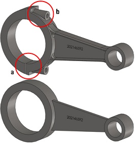
Marks will be allocated for creating a basic connecting rod model with these key dimensions, and bonus marks will be allocated for including additional detail, including fillets (2 marks), an I-beam cross section (2 marks), a split at the big end, shown at (a) on the example below (1 mark), and extruded cylinders to house the bolts, shown at (b) on the example below (1 mark). The part should be saved as one single .SLDPRT file (do not include the bolts themselves).
Your design must include your own Student Number etched onto the beam section, as a part number, using the ‘Text' tool (it will be invalid without this):
The figure below shows two possible connecting rod models. The top model contains enough detail to be awarded a relatively high mark in this part. The bottom model contains the minimum amount of detail to complete the rest of the assignment.
Remember the feedback from Semester 1: there are usually several ways of producing the same geometry, but there will always be one way which is easiest for any given part. Producing this model is possible using only the functions you have learnt in the exercises so far, plus the Text tool.
Part 2: Produce an Engineering Drawing of the Connecting Rod
Using the SolidWorks drawing function, produce a third angle projection drawing of the connecting rod model:
- Use the Sheet Format available in the Course Content area on Blackboard: ‘SolidWorks Part Drawing Sheet Format', and
- Edit the sheet format to include your Name, the Date, the Scale, and a name for the part
- Include a longitudinal section view through the part (HINT - which orientation gives most information?)
- Include sufficient dimensions that would allow somebody else to recreate the solid model
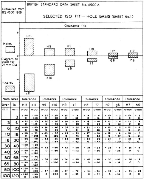
- Include tolerance ranges on the diameter dimensions at the Big and Little Ends to give a normal running fit (H8 - f7) with the crankshaft (nominal Ø59mm) and gudgeon pin (nominal Ø22mm) bearings. Give these in mm format, not the BS codes.
Remember the feedback from Semester 1: make your drawing as clear as possible, mark sections and details clearly, indicate where you are using multiple/typical dimensions, only include each dimension once, and avoid crossing-over dimension lines.
Part 3: Produce a Working Assembly of the Engine and Evaluate its Kinematics using a Motion Study
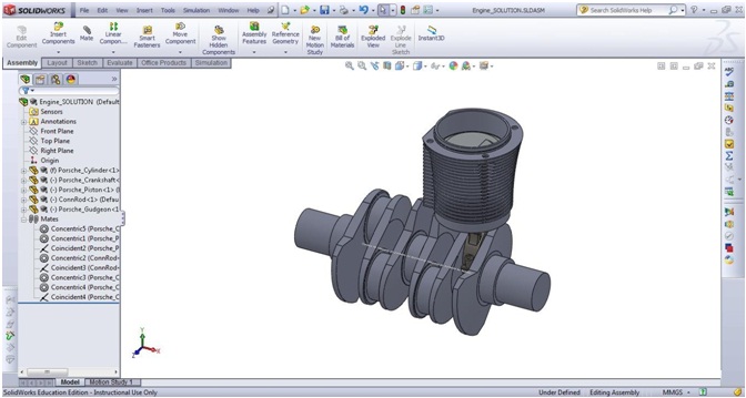
Download the parts ‘Porsche_Cylinder.sldprt', ‘Porsche_Piston.sldprt', ‘Porsche_Gudgeon.sldprt' and ‘Porsche_Crankshaft.sldprt', and the assembly ‘Engine.sldasm'. Open the assembly, which already contains the cylinder fixed at the origin, and a construction line marking the axis of rotation of the crank shaft. Add in the remaining components:
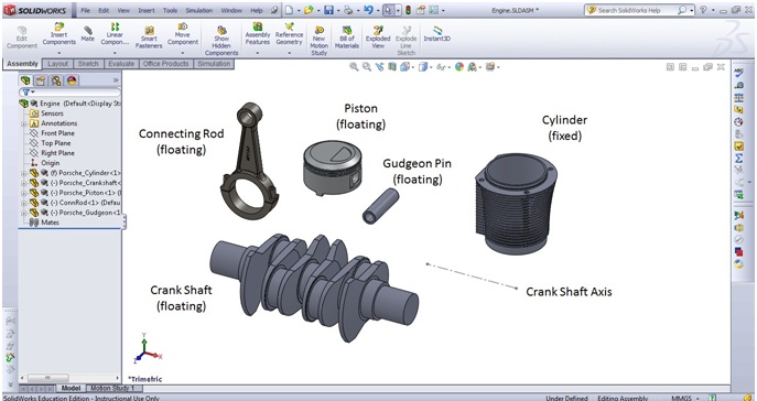
Create an appropriately constrained assembly by adding mates between the components, making the single cylinder ‘crank slider' mechanism. The assembly should be constrained so that by dragging and rotating the crank shaft, the piston slides in the cylinder. Think about what degrees of freedom need constraining.
Finally, using the theory from the MTB frame exercise this semester, use the SolidWorks Motion add-in to produce a Motion Study, and evaluate the engine's kinematics.
With your assembly model open, load the add-in (for this stage you will need to use a computer on campus, with a full Academic Licence).
To apply materials to the Piston, Gudgeon Pin and Connecting Rod parts, expand their names in the Feature Tree on the left, right click on ‘Material (not specified)' and select ‘Edit Material'. You will be able to find appropriate materials on-line, or in textbooks. Select materials that would be used in a normal road car, not a million pound racing car.
This applies a density to the components, allowing the inertial forces associated with their acceleration to be calculated. Next, click on the ‘Motion Study 1' tab, and set up a ‘Motion Analysis'.
Apply a ‘Motor' to the Crank Shaft, generating constant speed rotation at 60rpm. Calculate the Motion Analysis for a duration of 2 seconds, and review your results.
Finally, create five output measures to analyse your Motion Study results, and plot them on graphs:
- The y-displacement of the piston vs. time,
- The y-velocity of the piston vs. time,
- The y-acceleration of the piston vs. time,
- The y-reaction force in the little-end bearing of the connecting rod (with the gudgeon pin) and
- The y-reaction force in the big-end bearing of the connecting rod (with the crank shaft).
Give them sensible names so you can find them easily on the marking day. Marks will be awarded for:
- Demonstrating a running Motion Analysis of two full cycles of the mechanism,
- Use of appropriate materials,
- Showing on-screen your 5 results plots, named appropriately,
- Containing the correct magnitude y-axis results, and
- Scaling the y-axes on the Force Graphs to the same range (see over the page)
Example results plots (I have removed the y-axis values) are shown below. Note that the graphs will look different depending upon the start-point of the assembly when you run the calculation
Hint: Often there is a spike at the beginning of the analysis as it achieves a stable solution (which can be hidden by scaling the y-axis to an appropriate range)
Attachment:- A3_Drawing_Sheet_Format.rar