Assignment - Power Distribution System Transformers
Complete your calculations, drawings, and answers, neatly handwritten on these sheets and hand in at the start of lecture in week 6. Absolutely no late submissions will be accepted as we will be reviewing assignment solutions and the midterm review during the week 6 lecture.
Show your work and units. If necessary add any extra handwritten worksheets at the back and identify which question number the calculations are for.
Reference your course textbook: Electrical Machines, Drives, and Power Systems (by Theodore Wildi), particularly chapters 9, 10, 11, 12.
Do independent work, copy penalties will be strictly enforced. You don't learn by copying.
The total power in a 3 phase device, is the sum of the power in each phase. The power is supplied by a source, is passed through a transformer (usually with very low power loss in the transformer, often calculated as zero power consumption when the focus of the circuit analysis is on the load).
Circuit impedance (Z) is a phasor variable (amplitude and angle)
Z = R + j(XL -XC)
Apparent power (S) is also a phasor variable (amplitude and angle)
S = P + j(QL - QC)
Stotal = Sphase 1 + Sphase 2 + Sphase 3
Ptotal = Pphase 1 + Pphase 2 + Pphase 3
S = V X I in each phase
V/Z = I and ZI = V, therefore by substitution, S = I2Z = V2/Z
Real power is only from resistive circuit elements, P = I2R = V2/R
Reactive power is only from reactive circuit elements (inductors and capacitors), Q = I2X = V2/X
If the impedance is all resistive (no reactive elements of inductance or capacitance), then the power is all real and will be ‘Watts'. If there are inductors or capacitors, then there will be reactive power ‘VARs' (volt-amps reactive), and if both real and reactive power, then the total power is the apparent power ‘Volt-Amps or VA'. These three types of power create the AC power triangle and basic trigonometry is used to analyze reactive circuits. The power triangle of an electrical system is closely related to the impedance triangle. Remember that inductors have a positive reactance and capacitors have a negative reactance in the impedance triangle.
3 phase relationships:
Wye: I line = I phase, V line > V phase, V line =1.732 X Vphase
Delta: V line = V phase, I line > I phase, I line =1.732 X Iphase
In 3 phase transformers, the ‘Phase voltage and current' refers to the individual transformer coil values, and the ‘Line voltage and current' refers to the values in the feeder conductors.
1. The following questions refer to the 3 phase power distribution circuit below with a resistive load. The required power transformer 3 phase connection on the secondary must be different than on the primary:
a) The total power in the load circuit above is 90KW, what is the power per phase?
P phase =
b) Solve for VR (the phase voltage across each resistor), based on the resistor value per phase and the power per phase. VR = __________ /1
If the resistors are connected in delta what would be the line voltage of the load?
If the resistors are connected in wye what would be the line voltage of the load?
c) From the circuit above, the supply line voltage is 4160 V, and the rated transformer primary voltage is 2400 V (this will be the primary phase voltage of the 3 phase transformer).
What type of 3 phase connection must be used for the transformer primary (WYE or DELTA)?
d) In the above transformer with a 2400 V primary phase voltage, the transformer can be connected to have either a 120V (parallel) or 240V (series) secondary phase voltage with the available taps (for either voltage, connect so that you get the full transformer power capacity). Then the secondary phases can be connected in delta or wye for the 3 phase secondary line voltage.
What are the secondary line voltages for each possible transformer secondary connection?
Secondary phase voltage V line (delta) V line (wye) /4
120 V ____________ ____________
240 V ____________ ____________
e) Considering the above results, what must be the secondary phase and line voltages and the load resistors 3 phase connection? Remember that the specification requires that the secondary transformer connection must be different than the primary. The load connection is independent and can be either WYE or DELTA.
f) Draw in the wiring connections on the schematic circuit above to match the above stated conditions. Include the instrument transformer and connections that are required for power system measurements.
g) Draw and label the circuit in the 3 phase shape format (such as in question 6 below), with the source, power transformers, instrument transformers, and load:
h) Calculate the following:
a. resistor phase current
b. Secondary to load line current
c. Secondary phase current
d. Primary phase current
e. Primary line current
2. A transformer is rated at 4,600/115 volts. A voltmeter connected across the secondary reads 112 volts. What is the primary voltage (assume ideal transformer)?
3. A current transformer (CT) is rated at 150/5 amperes. An ammeter in the secondary circuit reads 3.5 amperes. What is the primary current (assume ideal transformer)?
4. A 2,300/115-volt potential transformer (PT) and a 100/5-ampere current transformer (CT) are connected on a single-phase power line. A voltmeter; an ammeter, and a wattmeter are connected to the secondaries of the instrument transformers. The voltmeter reads 100 volts, the ammeter reads 4 amperes, and the wattmeter reads 375 watts.
a) What is the actual line voltage?
b) What is the actual line current?
c) What is the actual line power?
5. What is the power factor of the single-phase circuit in question 4?
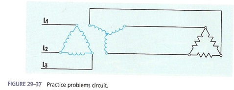
6. Solve the following circuit analysis: (12 marks total)
a) Complete the transformer circuit value table. Show your calculations.
Calculations:
b) What is the single phase transformer ratio in this circuit (phase to phase)?
c) What is the 3 phase transformer ratio in this circuit (line to line)?
7. Single phase transformer equivalent circuit. Reference Wildi Ch. 10
a) Draw and label the complete equivalent circuit of a single phase 5:1 practical transformer connected to a source of 600 VAC and load impedance of 60 ohms resistive.
b) What transformer circuit variables can be determined from each transformer test?(just the symbols and names, not the actual values)
i) Resistance tests: ___________________________________________ /2
ii) Open circuit test: ___________________________________________ /3
iii) Short circuit test: ___________________________________________ /2
iv) Loaded circuit test: ___________________________________________ /1
c) Open circuit measurements are V1= 600V, I = 50mA, P = 10W, what equivalent circuit component variables can be calculated and what are their values? Show your formulas used and calculation results.
d) Short circuit measurements are V1 = 25V, I1 = 2A, P1= 20W, determine the total combined equivalent circuit parameters as referenced on the primary side.
e) In some applications the transformer equivalent circuit can be simplified for easier practical analysis.
i) Under what conditions can you use the minimum equivalent circuit (one transformer circuit element)?
ii) Draw and label the minimum single phase transformer equivalent circuit which has only the voltage supply, one transformer equivalent circuit element, and one load element. (reference Wildi Ch.10)