Advanced structural analysis and design -
Numerical Analysis - FEM in application: using commercial FE software to model, analyse and design engineering structures.
Question 1: This question contains basic usage of AutoCAD and Strand7 with my instructions through steps. You should attempt this question first.
Context:
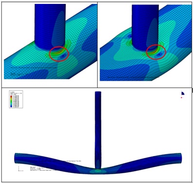
Circular hollow sections are commonly used in the construction of offshore steel oil and gas platforms as the shapewith its low drag coefficient and uniform lateral strength can minimize the hydrodynamic force and possess high torsionalrigidity. Below FEA extractions show the case of axial load through vertical member (brace). It is observe that stress concentration is most severe at the circled location (saddle location - intersection of the brace and the horizontal chord).
Learning outcomes:
This task will expose you to the current recommended practice for fatigue design of the offshore steel structures from Det Norske Vista (DNV) and its implementation when applying to research on the stiffened joint. You will develop skills about AutoCAD 2D and 3D surfaces generation; Strand7 FE mesh generation and refinement; Strand7 FEA and use of FEA to complete a specific oil and gas industry problem.
Pre-processing:
Task 1: Develop skills about basic CAD drawing.
Instruction for practice:
- Download free from AutoDesk website and install AutoCAD in personal computer (professional trial version is available for 30 days, student version is free for student usage for 3 years).
- Watch tutorial videos (Google, YouTube) for these commands: circle, pline, rotate3D, mirror3D. And in '3D modeling', under module 'Surface', these commands: planar, extrude, trim, slice.
Task to complete:
Given chord length L = 5000mm, brace length l = 1000mm, chord diameter (center-center of thicknesses) = 500 mm, brace diameter (center-center of thicknesses) = 300 mm.In AutoCAD 2D and 3D surfaces, use listed commands to generate the tubular geometry. Save the completed work as a ***.dwg file format and ***.igsfile format (also known as ***.iges file format).
Hints:
- We target at shell elements for FEA in the next stage. You do not need the thickness at this CAD drawing stage.
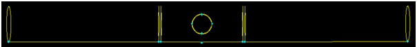
- For FEA in next stage, chord surface is split at 500 mm and 530 mm from centre on both sides similar as in below CAD drawing.
Pre-processing and post-processing:
Task 2: Develop skills for FE mesh generation and refinement; FEA including specifying material properties, applied load, restraint boundary conditions; complete the FEA procedure with solving the model using built in solver and judging the obtained results.
Tasks to complete:
- Import the given CAD model into Strand7.
- Apply thickness T = t = 10mm for chord, brace. Apply material as AS4100 steel.
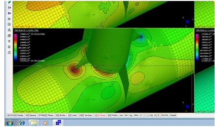
- For the region about the joint junction, apply element size of 10 mm. Use element subdivide for the elements at the transition region edge. Out of the junction region, the element can be coarser and you can nominate element size. Your element sizing should look like below figure.
- Apply 1 N axial load downward at the centre of the brace top opening. Use rigid links/rigid elements to connect the centre node to all element nodes on the rim.
- Apply fix end boundary for all element nodes on left opening and right opening of the chord.
- Save and solve the model with the built in "Linear Static" solver.
- Plot the deformation shape (exaggerated) and the VonMises stress contour. Comment if the obtained plots are reasonable and as expected for this problem.
- Report the displacement and Von Mises stress at saddle location.
- Download free "DNV RP C203. 2016. Fatigue of offshore structures." Compute the SCF for saddle location using Effthymiou's equations in the book. How much is it different from stress ratio (Von Mises saddle)/(Von Mises brace)? Discuss reasons for the discrepancy.
Question 2: This question introduces you to modelling with solid elements and sharpens your structural understanding for what should expect for mechanics of structural member that is non-symmetric.
Flexural analysis of Zee-section beam:
Cross-section is a zee-shape in the x-y plane as seen in below figure. Length extends in the z-direction.Cantilever beam, at free end is loaded with vertical, downward force of P = 1000N.
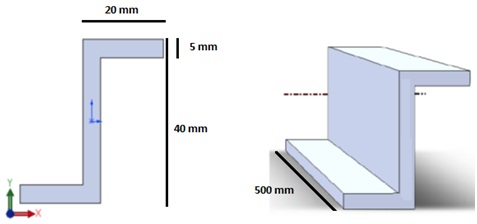
2. 1 Use the beam theory, draw BMD, SFD, normal stress diagram for cross section, shear stress diagram for cross section, strain diagram for cross section; compute free end deflection.
2. 2 In Strand7, model with solid Hexa8 elements of size 0.005m. Material: AS4100 Steel. Apply point load is ok in 2 different ways: a. Face → Global pressure; b. Node → Force
2.2.1 Solve with ‘Linear Static' solver, plot Von Mises stress contour, screen shot stress plot for fixed end. Is it what you expect from beam theory? If not, explain the reason why.
2.2.2 For deformation shape, is it what you expect from basic beam theory? If not, explain the reason why.
2.2.3 Report max deflection in X, Y, Z of free end. Compare with predicted deflection from beam theory. Report % of differences.
Overall, conclude about the application of beam theory and its constraints.
Question 3: This question shows you how to introduce compatibility at the truncated edges, especially for case of symmetric problem.
Plane stress flat plate, AS4100 structural steel, with uniaxial load and circular hole of diameter 200 mm at center:
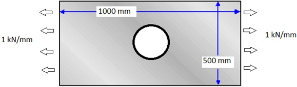
3.1 Generate CAD file and import surface in Strand7. Use shell elements to model the plate. It is a plane stress problem, specify degrees of freedom you need to restrain. Run ‘Linear Static' solver, report contour plot for principal stress in the loading direction.
3.2 To reduce the model size for saving computational effort, you now model one quarter only. What boundary condition do you have to apply to the horizontal cut and the vertical cut to maintain structure compatibility at the cuts?
Run ‘Linear Static' solver, report contour plot for principal stress in the loading direction. You should have the same results as obtained in 3.1.