Advanced Communication Systems Assignment
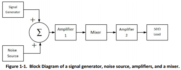
Q1. As shown in figure 1-1, the output of a noise source and the output of a signal generator are summed together. The resulting signal plus noise is the input of a system. The system consists of the cascade combination of:
Amplifier 1, a mixer (two port frequency converter), and amplifier 2. The block diagram of this system is shown in figure 1-1.
The signal is a bandpass modulated signal with a 1 MHz bandwidth.
The centre frequency of the signal is 900 MHz.
Amplifier 1 and amplifier 2 have bandpass transfer function characteristics. Amplifier 1 has a centre frequency of 900 MHz. The mixer down-converts a 900 MHz signal to 100 MHz. Amplifier 2 has a centre frequency of 100 MHz. Both amplifier 1 and amplifier 2 have noise equivalent bandwidths of 10 MHz. The amplified and frequency converted signal does not have any signal distortion at the 50 Ω load resistor.
The noise source has a noise temperature 2,000 Kelvin.
The three devices are specified by:
amplifier 1, Noise Figure=1.4 dB, Gain=15 dB,
mixer, Noise Figure= 13 dB, Gain= 6 dB,
amplifier 2, Noise Figure=16.0 dB, Gain=60 dB.
It is required to have a signal to noise ratio, (Ps/Pn)dB = 16 dB, at the 50 Ω load resistor at the output of amplifier 2, where Ps is the signal power and Pn is the noise power.
Part A -
To achieve this, what is the required RMS (root mean square) signal level at the signal generator output in volts? Note, the output of the signal generator is measured across a 50 Ω resistive impedance.
Part B -
Corresponding to the signal generator output that achieves (Ps/Pn)dB = 16 dB, what is the rms voltage at the output of amplifier 2 in volts?
Q2. A bandpass radio signal s(t) has complex envelope representation,
s(t) = Re[s~(t)ej2πf_ct]
where,
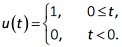
s~(t) = Aejθe-at u(t)
The signal is put through a bandpass filter with impulse response h(t), where,
h(t) = Re[h~(t)ej2πf_ct]
where h~(t) = CejΦe-βt u(t)
What is the output of the filter, y(t) as a function of t , A, C, α, β, θ and Φ?
Hint: y(t) = ½Re[y~(t)ej2πf_ct], where y~(t) = s~(t)*h~(t) and * is the convolution operator.
Q3. A communication system uses QPSK modulation.
The bit error rate requirement for this system is PB = 10-6.
The transmission frequency is fo = 2.4 GHz.
The transmitter power is 1 Watt.
The feed line loss between the transmitter and the transmit antenna is 2 dB.
The transmit antenna is omnidirectional and has a gain of 0 dBi.
The transmit antenna height is 20 meters
For the receiver, the low noise amplifier has a noise figure of 7 dB, the feedline loss is 1.5 dB, the antenna temperature is 290 K, and the receive antenna gain is 3 dBi. The demodulator implementation loss is 1 dB. The receive antenna height is 1.5 meters.
A. Assuming free space loss in the channel, plot the data rate that the link supports for distances between 100 meters and 20 km. Use a log-log graph to plot the data rate in bits/s as a function of distance, d, in meters.
B. Assuming a two-ray propagation loss model, plot the data rate that the link supports from dc to 20 km, where dc = 4hthr/λ = 4hthrfo/c.
On the same graph as part A, plot the data rate in bits/s as a function of distance, d, in meters.