Ask Question, Ask an Expert

+61-413 786 465

info@mywordsolution.com

Ask Electrical & Electronics Expert

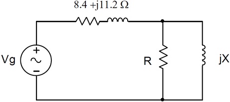
problem: A single phase line has an impedance of 8.4 + j11.2 Ω. The line feeds a load comprising of a resistor and an inductor connected in parallel as shown in figure below. The load is absorbing 30kVA at 0.6 power factor lagging. The load voltage is 1200Vrms.

Find out:

a) The values of R and X,
b) The supply current Ig and the supply voltage Vg,
c) Total real and reactive power loss in the line.
415_Single phase line.jpg


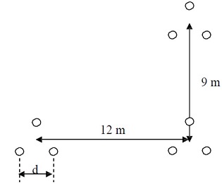
problem: A 300 km, 3-phase, 50Hz transmission line has spacing as shown in figure below. Each phase of the line comprises of a bundle of three conductors.

a) Determine the total per-phase inductance and the total per-phase shunt capacitance of the line if the conductors have diameter of 2.4cm and a GMR of 0.88cm. Suppose bundle spacing d = 0.4m.

b) Determine the percentage change of resistance, inductance and the capacitance if the line is altered by adding up one more conductors of the similar size and type to the bundle.

c) Use Matlab to check your results in (a) and ( b). Comment if the outcomes agree or not.
34_transmission line spacing.jpg

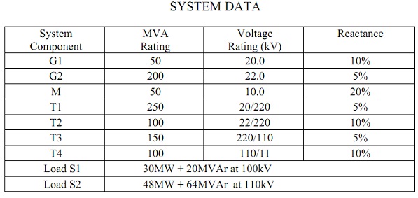
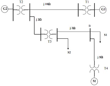
problem: The one line diagram of a simple power system is described below. The data of the system are given in the table shown below.

a) Draw the impedance diagram of the system and mark all impedances in pu on the diagram. Choose a base of 100 MVA and 20kV at generator G1.

b) find out the pu voltage and line to line voltage of bus B if the motor draws its rated power at its rated voltage and power factor 0.8 lagging.
889_simple power system table.jpg

2366_simple power system.jpg

problem: The 3-phase transmission line is 200km long. The line has a per phase series impedance of 0.25 + j0.45 Ω/km and shunt admittance of j7.2 μS/km. The line delivers 250MVA, at 0.6 lagging power factor and 120V to a 3-phase load.

a)  Find out ABCD parameters of the line.

b)  Determine the sending end voltage, sending end current, voltage regulation and the efficiency of the line.

c)  Find out the capacitance per-phase of the Y–connected capacitors to adjust the power factor of the load to unity and compute the voltage regulation and the line efficiency in this case.

problem: For the 3 bus system described below all values are given in pu on a 100MVA base.

a) Use Matlab functions lfgauss and lfnewton to determine power flow solution for the system, accurate to 0.0000001pu. Compare the 2 techniques.

b) Draw the power flow diagram exhibiting voltages and powers for all busses and power losses in all lines.
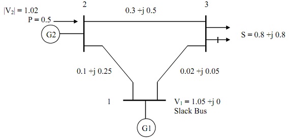
2129_power flow diagram.jpg

problem: The one line diagram of a simple three-bus power system is shown in the figure below.  Each generator is symbolized by an emf behind the transient reactance. All impedances are expressed in per unit on a common 100 MVA base, and for simplicity, resistances are neglected. The given suppositions are made:

A) Shunt capacitances are neglected and the system is considered on no-load.

B) All generators are running at their rated voltage and rated frequency with their emfs in phase.

Find out the fault current, the bus voltages, and the line currents during the fault when:

(i) A balanced three-phase fault with fault impedance Zf = j0.02 pu occurs on bus 1;

(ii) A bolted 3-phase fault occurs on bus 3.

89_Fault current.jpg

Electrical & Electronics, Engineering

  • Category:- Electrical & Electronics
  • Reference No.:- M9315

Have any Question? 


Related Questions in Electrical & Electronics

Case studythis assignment consists of a written report of

CASE STUDY This assignment consists of a written report of approximately 1000 words and any diagrams in which you are asked to critically compare different process methods used to achieve the same result and show an awar ...

Questions -problem 1 - a series rlc network has r 2 komega

Questions - Problem 1 - A series RLC network has R = 2 kΩ, L = 40 mH and C = 1μF. Calculate the impedance at resonance and at one-fourth, one-half, twice, and four times the resonant frequency. Problem 2 - Design a serie ...

Electrical engineering questions -q1 two ideal voltage

Electrical Engineering Questions - Q1. Two ideal voltage sources designated as machines 1 and 2 are connected, as shown in the figure below. Given E 1 = 65∠0 o V, E 2 = 65∠30 o V, Z = 3Ω. Determine if Machine 1 is genera ...

Question 1 in the voltage regulator circuit in figure p221

Question 1: In the voltage regulator circuit in Figure P2.21, V 1 = 20 V, V Z = 10 V, R i = 222Ω and P z (max) = 400 mW. (a) Determine I L, I z , and I L , if R L = 380Ω. (b) Determine the value of R L , that will establ ...

Assignment -problem 1 -a consider the simplified dc system

Assignment - Problem 1 - a) Consider the simplified dc system shown in Fig. 1. Only one converter is modeled, with the remote end represented by a dc source. The ac system is rated at 345 kV, with the converter transform ...

Questions -q1 a single-phase transformer rated 21 kv130 v

Questions - Q1. A single-phase transformer rated 2.1 kV/130 V, 7.8 kVA has the following winding parameters: r1= 0.7Ω, x1 = 0.9Ω, r2 = 0.04Ω and x2 = 0.05Ω. Determine: a. The combined winding resistance ________ Ω and le ...

Questions -problem 1 - determine the laplace transform ofa

Questions - Problem 1 - Determine the Laplace transform of: (a) cos(ωt + θ) (b) sin(ωt + θ) Problem 2 - Obtain the Laplace transform of each of the following functions: (a) e -2t cos(3t)u(t) (b) e -2t sin(4t)u(t) (c) e - ...

Research report1 read 3 to 4 journal articles about digital

Research report 1. Read 3 to 4 journal articles about digital control or industrial control, eg. one particular application, implementation aspect such as selection of sampling time, hardware etc. No text book example is ...

Question 1for the ce amplifier in figure 1 given the

Question 1 For the CE amplifier in Figure (1), given the following component parameters: Parameter Value β DC , β AC 150 V BE 0 . 7 V V CC 12 V R C 820 ? R E 1 100 ? R E 2 220 ? R 1 20 k? R 2 5 . 2 k? R L 100 k? C 1 , C ...

1 a name the three major groups of contamination and

1. (a) Name the three major groups of contamination and briefly describe their physical characteristics. (b) Where do the above contamination types come from? Give one example of each. 2. Name two processes metrics which ...

  • 4,153,160 Questions Asked
  • 13,132 Experts
  • 2,558,936 Questions Answered

Ask Experts for help!!

Looking for Assignment Help?

Start excelling in your Courses, Get help with Assignment

Write us your full requirement for evaluation and you will receive response within 20 minutes turnaround time.

Ask Now Help with Problems, Get a Best Answer

Why might a bank avoid the use of interest rate swaps even

Why might a bank avoid the use of interest rate swaps, even when the institution is exposed to significant interest rate

Describe the difference between zero coupon bonds and

Describe the difference between zero coupon bonds and coupon bonds. Under what conditions will a coupon bond sell at a p

Compute the present value of an annuity of 880 per year

Compute the present value of an annuity of $ 880 per year for 16 years, given a discount rate of 6 percent per annum. As

Compute the present value of an 1150 payment made in ten

Compute the present value of an $1,150 payment made in ten years when the discount rate is 12 percent. (Do not round int

Compute the present value of an annuity of 699 per year

Compute the present value of an annuity of $ 699 per year for 19 years, given a discount rate of 6 percent per annum. As