Ask Question, Ask an Expert

+61-413 786 465

info@mywordsolution.com

Ask Electrical & Electronics Expert

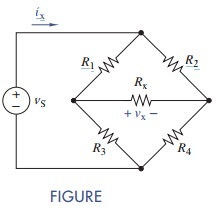
(a) Formulate node-voltage equations for the bridge circuit in Figure.

(b) Solve for vx and ix when R1 = R4 =1kΩ, R2 = R3 = 1:5 kΩ, Rx = 680 Ω, and vS = 12 V.

(c) Repeat (b) when R4 is a variable resistor that varies from 10 Ω to 10 kΩ. At what value of R4 is the voltage across Rx = 0 V? Use Multisim to find the value by either varying R4 by trial and error to approach the answer, or using a "Parameter sweep" found under Analyses.

To use the latter, proceed as follows: Under "Parameter sweep" select "Device type:" Resistor; "Name:" your name for our R4; "Parameter (what you wish to vary):" resistance; "Present value:" Any value within your range-say, 1 kΩ. Under "Points to sweep," choose "Linear" sweep variation type. "Start" at 10 Ω; "Stop" at 10 kΩ. Use 100 points-Multisim automatically calculates the increment. Under "More Options" choose "DC Operating Point." Then go to the output tab under the Parameter Sweep window.

Since you want the voltage across the 680-Ω resistor, create an expression for it, such as V (2)-V (3) if those are the node names of the two nodes determining the voltage. Choose "Simulate." Grapher View will plot a graph of the resistance value versus the voltage across the 680-Ω resistor. Make sure the grid lines are shown on your graph. Use the cursor to find the value of resistance that causes the voltage to go to zero.
1747_Figure 1.jpg

Electrical & Electronics, Engineering

  • Category:- Electrical & Electronics
  • Reference No.:- M92049886

Have any Question?


Related Questions in Electrical & Electronics

1 goalin this project you will solve a non-trivial design

1 Goal In this project you will solve a non-trivial design problem explicitly using the divide-and-conquer (D&C) approach. The main reason for using the D&C approach is the ease of the design process and the streamlined ...

1 a name the three major groups of contamination and

1. (a) Name the three major groups of contamination and briefly describe their physical characteristics. (b) Where do the above contamination types come from? Give one example of each. 2. Name two processes metrics which ...

Discuss the role of load factor on the cost of electrical

Discuss the role of load factor on the cost of electrical energy.

Questions -problem 1 - given the sinuosidal voltage vt 50

Questions - Problem 1 - Given the sinuosidal voltage v(t) = 50 cos(30t+10 o ) V, find: (a) the amplitude V m (b) the period T, (c) the frequency f and (d) v(t) at t = 10 ms. Problem 2 - A current source in a linear circu ...

Questions -problem 1 - a series rlc network has r 2 komega

Questions - Problem 1 - A series RLC network has R = 2 kΩ, L = 40 mH and C = 1μF. Calculate the impedance at resonance and at one-fourth, one-half, twice, and four times the resonant frequency. Problem 2 - Design a serie ...

Problem 1given a sequence xn for 0lenle3 where x0 1 x1 1

Problem # 1: Given a sequence x(n) for 0≤n≤3, where x(0) = 1, x(1) = 1, x(2) = -1, and x(3) = 0, compute its DFT X(k). (Use DFT formula, don't use MATLAB function) Problem # 2: Use inverse DFT and apply it on the Fourier ...

1 a name the three major groups of contamination and

1. (a) Name the three major groups of contamination and briefly describe their physical characteristics. (b) Where do the above contamination types come from? Give one example of each. 2. Name two processes metrics which ...

Nanotechnology engineering - resonance circuits questions

Nanotechnology Engineering - Resonance Circuits Questions - Q1) A series RLC network has R = 2KΩ, L = 40mH and C = 1μF. Calculate the impedance at resonance and at one-fourth, one-half, twice, and four times the resonant ...

Questions -problem 1 - solve for i0 in fig using mesh

Questions - Problem 1 - Solve for i 0 in Fig. using mesh analysis. Problem 2 - Use mesh analysis to find current i 0 in the circuit. Problem 3 - Use mesh analysis to find v 0 in the circuit. Let v s1 = 120 cos(100t+ 90 o ...

Question 1 in the voltage regulator circuit in figure p221

Question 1: In the voltage regulator circuit in Figure P2.21, V 1 = 20 V, V Z = 10 V, R i = 222Ω and P z (max) = 400 mW. (a) Determine I L, I z , and I L , if R L = 380Ω. (b) Determine the value of R L , that will establ ...

  • 4,153,160 Questions Asked
  • 13,132 Experts
  • 2,558,936 Questions Answered

Ask Experts for help!!

Looking for Assignment Help?

Start excelling in your Courses, Get help with Assignment

Write us your full requirement for evaluation and you will receive response within 20 minutes turnaround time.

Ask Now Help with Problems, Get a Best Answer

Why might a bank avoid the use of interest rate swaps even

Why might a bank avoid the use of interest rate swaps, even when the institution is exposed to significant interest rate

Describe the difference between zero coupon bonds and

Describe the difference between zero coupon bonds and coupon bonds. Under what conditions will a coupon bond sell at a p

Compute the present value of an annuity of 880 per year

Compute the present value of an annuity of $ 880 per year for 16 years, given a discount rate of 6 percent per annum. As

Compute the present value of an 1150 payment made in ten

Compute the present value of an $1,150 payment made in ten years when the discount rate is 12 percent. (Do not round int

Compute the present value of an annuity of 699 per year

Compute the present value of an annuity of $ 699 per year for 19 years, given a discount rate of 6 percent per annum. As