Ask Question, Ask an Expert

+61-413 786 465

info@mywordsolution.com

Ask Electrical & Electronics Expert

1. With reference to the block diagram of FIGURE 1, state the two conditions that must be satisfied to give an oscillatory output.
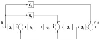
1873_figure1.jpg

FIG. 1

2. With reference to the block diagram of FIGURE 1, determine the required value of G to give an oscillatory output if H = -10 dB.

3. FIGURE 2 shows a public address system.

(a) It is found that if the microphone is brought into proximity of the loudspeaker, the systems will ‘howl'. Carefully explain, making reference to feedback theory why this is so.

(b) Suggest two actions that could be adopted to remedy the ‘howling'.

(c) Measurements show that for a particular arrangement of the equipment and at a particular amplifier setting, the system will howl if 1% of the output power is fed back to the microphone. Estimate the power gain of the P.A. amplifier in decibels.
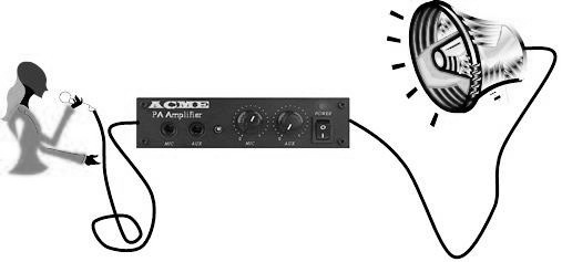
686_figure2.jpg

FIG. 2

4. FIGURE 3(a) shows the circuit of an Armstrong oscillator (named after its inventor, the American engineer Edwin Armstrong in 1912). Here a transformer is used to couple the output to the input to give feedback. The transformer has a turns ratio of n:1, where n represents the primary winding.

In this particular circuit the transistor's emitter resistor is bypassed by a large capacitor at a.c. frequencies and its base is biased via the transformer windings.

FIGURE 3(b) represents the a.c. equivalent circuit of the oscillator and (c) its h-parameter equivalent circuit.

(a) Explain the significance of the transformer's dot notation in relation to the operation of the oscillator.

(b) It can be shown that the loop-gain of the oscillator at resonance is given by:

|Gloop-gain| = 1/n.(hfe/hie).R'L

where RL′ is the effective resistive load on the transistor, i.e.:

RL′ = RL //hoe // n2 ( R1 //R2 )

Estimate the required value of turns-ratio if:

R1 = 4.7 k?, R2 = 24 k?, RL = 2.7 k?, hfe = 250, hoe = 10-5 S, hie = 4 k?
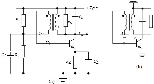
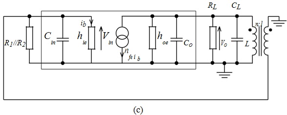
1496_figure3.jpg

1820_figure4.jpg

Fig.3

5. FIGURE 4 shows another variation the Armstrong oscillator. A transformer with two secondary windings has been use, one to give feedback and one to give the oscillator's output.

Write a short report [two to three pages] on an investigation into the operation and performance of this circuit1.

The report should embrace, as far as you are able, the following themes:

(a) Why the output is taken via the transformer rather than directly off the collector of the transistor.

(b) The agreement between the measured and calculated quiescent voltages on the three terminals of the transistor.

(c) The agreement between the measured and calculated frequency of oscillation.

(d) The shape of the output waveform in the first 10 milliseconds of start-up.

(e) The given L1:L2 ratio is not necessarily the optimum value to give a good sinusoidal output. [A Fourier probe on the output will give a spectral response]. Try to devise an experiment to find the optimum ratio*. Express the ratio as a turns ratio.

The report should include copies of any graphical responses produced in the investigation.

*This can be done by performing an AC sweep on the inductance parameter L2. However a sweep cannot be performed without a voltage source in the circuit. For the purposes of this analysis a small voltage source can be inserted into the feedback loop as shown in the second version of the circuit on Blackboard.

1732_figure.jpg

Fig.4

Electrical & Electronics, Engineering

  • Category:- Electrical & Electronics
  • Reference No.:- M92868573
  • Price:- $50

Priced at Now at $50, Verified Solution

Have any Question?


Related Questions in Electrical & Electronics

Electrical engineering questions -q1 two ideal voltage

Electrical Engineering Questions - Q1. Two ideal voltage sources designated as machines 1 and 2 are connected, as shown in the figure below. Given E 1 = 65∠0 o V, E 2 = 65∠30 o V, Z = 3Ω. Determine if Machine 1 is genera ...

Nanotechnology engineering program assignment - passive

Nanotechnology Engineering Program Assignment - Passive Filters Q1) Determine what type of filter is in circuit shown. Calculate the cutoff frequency f c . Q2) Determine what type of filter is in circuit shown. Calculate ...

Discuss the role of load factor on the cost of electrical

Discuss the role of load factor on the cost of electrical energy.

Problem 1 a two-phase servomotor has rated voltage applied

Problem 1: A two-phase servomotor has rated voltage applied to its excitation winding. The torque speed characteristic of the motor with Vc = 220 V, 60 Hz applied to its control phase winding is shown in Fig.1. The momen ...

Question 1 in the voltage regulator circuit in figure p221

Question 1: In the voltage regulator circuit in Figure P2.21, V 1 = 20 V, V Z = 10 V, R i = 222Ω and P z (max) = 400 mW. (a) Determine I L, I z , and I L , if R L = 380Ω. (b) Determine the value of R L , that will establ ...

Problem 1given a sequence xn for 0lenle3 where x0 1 x1 1

Problem # 1: Given a sequence x(n) for 0≤n≤3, where x(0) = 1, x(1) = 1, x(2) = -1, and x(3) = 0, compute its DFT X(k). (Use DFT formula, don't use MATLAB function) Problem # 2: Use inverse DFT and apply it on the Fourier ...

Questions -q1 a single-phase transformer rated 21 kv130 v

Questions - Q1. A single-phase transformer rated 2.1 kV/130 V, 7.8 kVA has the following winding parameters: r1= 0.7Ω, x1 = 0.9Ω, r2 = 0.04Ω and x2 = 0.05Ω. Determine: a. The combined winding resistance ________ Ω and le ...

Question 1 a pnp transistor withnbspbeta 60 is connected

Question 1. A pnp transistor with β = 60 is connected in a common-base configuration as shown in figure P5.8 (a) The emitter is driven by a constant-current source with I E = 0.75 mA. Determine I B , I C , α, and V C . ( ...

Assignment -consider a common emitter amplifiernow lets say

Assignment - Consider a common emitter amplifier: Now let's say that R B and R C do a fine job at DC biasing the BJT but they are large so they can be neglected for small signal (AC) analysis. In that case, the equivalen ...

Questions -problem 1 - given the sinuosidal voltage vt 50

Questions - Problem 1 - Given the sinuosidal voltage v(t) = 50 cos(30t+10 o ) V, find: (a) the amplitude V m (b) the period T, (c) the frequency f and (d) v(t) at t = 10 ms. Problem 2 - A current source in a linear circu ...

  • 4,153,160 Questions Asked
  • 13,132 Experts
  • 2,558,936 Questions Answered

Ask Experts for help!!

Looking for Assignment Help?

Start excelling in your Courses, Get help with Assignment

Write us your full requirement for evaluation and you will receive response within 20 minutes turnaround time.

Ask Now Help with Problems, Get a Best Answer

Why might a bank avoid the use of interest rate swaps even

Why might a bank avoid the use of interest rate swaps, even when the institution is exposed to significant interest rate

Describe the difference between zero coupon bonds and

Describe the difference between zero coupon bonds and coupon bonds. Under what conditions will a coupon bond sell at a p

Compute the present value of an annuity of 880 per year

Compute the present value of an annuity of $ 880 per year for 16 years, given a discount rate of 6 percent per annum. As

Compute the present value of an 1150 payment made in ten

Compute the present value of an $1,150 payment made in ten years when the discount rate is 12 percent. (Do not round int

Compute the present value of an annuity of 699 per year

Compute the present value of an annuity of $ 699 per year for 19 years, given a discount rate of 6 percent per annum. As