Ask Electrical & Electronics Expert

Assignment -

Aim: Design a two-stage inverter circuit shown in Fig.1. The work will initially involve calculating respective dimensions of the different devices within the circuit (i.e. A, B, C and RL), using appropriate equations and parameters/constants provided below. Subsequently, respective layouts for each of the devices, and the overall circuit including interconnects and contact pads, needs to be generated accurately, on scaled or graph paper/s with stipulated scale (e.g. 1µm = 1cm). Make sure to accurately include the alignment error between layouts and utilise minimal area by arranging the layouts appropriately. All dimensions and areas of the layouts must be expressed in terms of the minimum feature size given below.

1730_figure.png

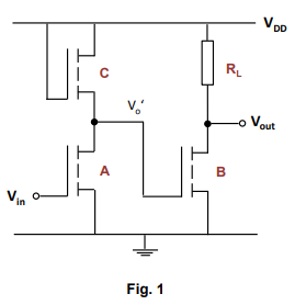
Description: The circuit in Fig. 1 consists of a two-stage inverter, where the intermediated output from the 1st inverter Vo' feds into the input gate of the 2nd inverter. The input and output of this circuit is Vin and Vout respectively. The driver of both of the inverters consists of enhancement type n-MOS transistors A and B. It can assume that these transistors have the same aspect ratio (W/L), and threshold voltage of 0.3 V.

The load device of the 1st inverter is an (active) saturated n-MOS transistor C, whilst the 2nd inverter has a (passive) implanted resistor load RL. Note the resistance of C can be assumed to be equal to that of RL, and similarly, the resistance of A is identical to the resistance of B, when the transistors are on. However note the dimension of C is not the same as RL since they are different devices. Refer to the p-n junction (passive load) notes to work out dimensions for RL, assuming a sheet resistance for the technology given below.

And to assist you with the calculation for the transistor dimensions, assume a logic 1 input to A, and thus select appropriate value for the intermediate output voltage Vo', to correspond to logic 0. Note this value of Vo' for logic0 needs to be lower than threshold voltage of the driver B so as to ensure that the transistor remains off at logic 0.

Note for the layouts you must take into account the alignment accuracy λa, which can also be assumed to be equal to the minimum feature size or multiple of it. Below are respective parameter values to be used in the calculation:

i. Minimum feature size λm = 0.5 µm

ii. Supply voltage VDD = 5V (Logic 1 input)

iii. Threshold voltage of transistors, VT = 0.3 V

iv. Sheet resistance 150 Ω/square

v. Device constant is given as below; note mobility μ and gate capacitance Co can be assumed to be the same for all transistors.

β = (μCo) W/L = (βo)W/L, where βo = 1.8 x 10⁻⁴ AV-2.

Report: Provide a brief description of the circuit operation in Fig. 1. Include all calculations and justification to any assumptions made. Represent all respective individual design layouts for A, B, C and RL, and the overall layout on scaled graph papers, and in terms of the minimum feature size. Use different shading to indicate different regions and include appropriate alignment errors between respective layouts. Make sure to utilise the area effectively particularly on the overall layout where the interconnects and contact pads need to be included.

Useful hints:

1. Initially focus on the first inverter and assume a logic 1 input. Note load C is always on and saturated, whilst with a logic 1 input to the driver A, this transistor is also on, and thus the current flowing between the two devices will be the same. Consequently, using appropriate drain current expressions for the two transistors, determine the ratio of the aspect ratios of the driver to the load. You will need to select appropriate values, ensuring the same ratio is maintained.

2. The resistance values for the two loads are the same i.e. RC = RL. To determine their dimensions i.e. L and W, of the implanted resistor RL, use the given the sheet resistance and consequently calculate the number of squares required.

Electrical & Electronics, Engineering

  • Category:- Electrical & Electronics
  • Reference No.:- M92795015

Have any Question?


Related Questions in Electrical & Electronics

Question 1for the ce amplifier in figure 1 given the

Question 1 For the CE amplifier in Figure (1), given the following component parameters: Parameter Value β DC , β AC 150 V BE 0 . 7 V V CC 12 V R C 820 ? R E 1 100 ? R E 2 220 ? R 1 20 k? R 2 5 . 2 k? R L 100 k? C 1 , C ...

Question -i a star-connected three-phase synchronous

Question - (i) A star-connected, three-phase synchronous induction motor takes a current of 10 amps from a 415 volt supply at unity power factor when supplying a steady load. If the synchronous reactance is 5 ohms/phase ...

1 a name the three major groups of contamination and

1. (a) Name the three major groups of contamination and briefly describe their physical characteristics. (b) Where do the above contamination types come from? Give one example of each. 2. Name two processes metrics which ...

Question 1 in the voltage regulator circuit in figure p221

Question 1: In the voltage regulator circuit in Figure P2.21, V 1 = 20 V, V Z = 10 V, R i = 222Ω and P z (max) = 400 mW. (a) Determine I L, I z , and I L , if R L = 380Ω. (b) Determine the value of R L , that will establ ...

Summative assessmentin 2017 sej101 assessment will consist

Summative Assessment In 2017 SEJ101 assessment will consist of nine tasks that will develop a portfolio of your assessed work. Throughout the trimester you will have the opportunity for feedback on all nine tasks before ...

1 a name the three major groups of contamination and

1. (a) Name the three major groups of contamination and briefly describe their physical characteristics. (b) Where do the above contamination types come from? Give one example of each. 2. Name two processes metrics which ...

1 a name the three major groups of contamination and

1. (a) Name the three major groups of contamination and briefly describe their physical characteristics. (b) Where do the above contamination types come from? Give one example of each. 2. Name two processes metrics which ...

Case studythis assignment consists of a written report of

CASE STUDY This assignment consists of a written report of approximately 1000 words and any diagrams in which you are asked to critically compare different process methods used to achieve the same result and show an awar ...

Problem 1 a two-phase servomotor has rated voltage applied

Problem 1: A two-phase servomotor has rated voltage applied to its excitation winding. The torque speed characteristic of the motor with Vc = 220 V, 60 Hz applied to its control phase winding is shown in Fig.1. The momen ...

Electrical engineering questions -q1 two ideal voltage

Electrical Engineering Questions - Q1. Two ideal voltage sources designated as machines 1 and 2 are connected, as shown in the figure below. Given E 1 = 65∠0 o V, E 2 = 65∠30 o V, Z = 3Ω. Determine if Machine 1 is genera ...

  • 4,153,160 Questions Asked
  • 13,132 Experts
  • 2,558,936 Questions Answered

Ask Experts for help!!

Looking for Assignment Help?

Start excelling in your Courses, Get help with Assignment

Write us your full requirement for evaluation and you will receive response within 20 minutes turnaround time.

Ask Now Help with Problems, Get a Best Answer

Why might a bank avoid the use of interest rate swaps even

Why might a bank avoid the use of interest rate swaps, even when the institution is exposed to significant interest rate

Describe the difference between zero coupon bonds and

Describe the difference between zero coupon bonds and coupon bonds. Under what conditions will a coupon bond sell at a p

Compute the present value of an annuity of 880 per year

Compute the present value of an annuity of $ 880 per year for 16 years, given a discount rate of 6 percent per annum. As

Compute the present value of an 1150 payment made in ten

Compute the present value of an $1,150 payment made in ten years when the discount rate is 12 percent. (Do not round int

Compute the present value of an annuity of 699 per year

Compute the present value of an annuity of $ 699 per year for 19 years, given a discount rate of 6 percent per annum. As