Assignemnt: DC POWER SUPPLY:
Find the DC power supply associated with your workbench. Using the proper cables, connect the DC power supply to a voltage meter. Be sure you change the meter from measuring resistance to actually measure voltage. Using the controls on the DC Power supply, adjust the output voltage to 5V and to 10V. Notice that you may need to use different outputs to get the desired 0V-10V range. Show the instructor that you can set the voltage to 10V and 5V.
OHMS LAW:
Select two resistors from the resistor selection bins. The first resistor must be 1W or 10W. This resistor will be used as a "current sense" resistor, called Rs. Then select another resistor, R1, that is within the range 1kW - R1 - 50kW.
1. Measure, with a Multimeter, the resistance values of R1 and Rs.
2. Connect R1 and Rs in series on the breadboard.
3. Now measure the total series resistance. Does the Rs resistance "really" impact the total resistance?
4. Make sure the power is off to the DC power supply. Then connect the positive DC voltage terminal to R1. Then connect the ground (GND) DC voltage terminal to the Rs using a combination of cables and wires.
5. Calculate, using Ohms law, how much current you expect to flow through R1, if the DC voltage is 5V. Record this value and the equation you used.
6. Ensure the DC voltage is still 5V. Then measure the voltage across Rs. Using your recorded resistance value and measured voltage, calculate the current through R1. Does it match your calculations in step 5?
7. Show your results to the instructor and get signoff.
8. Turn off the DC power supply.
Potentiometer Part A:
Obtain a 10K potentiometer and complete the following tasks, first with no DC Power connected.
1. Measure and record the total resistance across the device. (i.e. the outer terminals).
2. Turn the "knob" on the potentiometer. Does the total resistance change?
3. Measure the resistance between an outer terminal of the potentiometer and the middle terminal, as you adjust the "knob".
a. What is the minimum resistance you measure
b. What is the maximum resistance?
4. Adjust the resistance between an outer terminal and the middle terminal so it is 5KW.
Show your results to the instructor and get signoff.
Potentiometer Part B:
Now, apply 5V DC across the potentiometer and measure the voltage from the middle terminal to the ground side of the potentiometer, we will call this the output voltage. Answer the following questions:
1. What is the output voltage if the potentiometer was left at the 5KW position defined in the previous section?
2. What do you expect the minimum output voltage to be? What do you expect the maximum to be?
3. Turn the knob and validate your results from the previous step.
4. Disconnect the DC power supply and then measure the output resistance at the point where your output voltage reaches its minimum. What is the value of this resistance? Does this value make sense to you?
3B report Example :
Why this is a solid 3B Report
1) It is not a short lab report
2) It is concise, covers the key learning objectives, is technically detailed, and has the right balance between the three required components (Objectives, Accomplishments, Next Steps)
Improvements Needed
1) Grammar / Editing
2) Sentence Flow
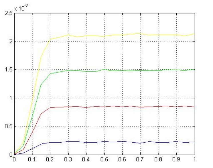
We explored the transistor 2N3904's three active regions. We analyzed how the measured parameters of junction's currents and voltages on how it affected its characteristics. We computed the beta value from the measured values.
We build a circuit capable of applying variable voltage across the BJT's baseemitter terminals. Our measured and theoretical I-V values confirmed that all three regions of operation were correct. Our I-V plot characteristic matched the BJT's datasheet within 5%. In figure1, with increasing fixed IB the IC slightly changed with VCE, causing the I-V curve to had non-zero slope in the active region. If the I-V curves slope were extended to the left, our early voltage would be around 200. This was a good transistor because of its wide dc-bias range region. Our circuit exhibited different beta levels from 180 to 220, thus our circuit bias point was sensitive and dependent to the transistor's beta. The beta governed our circuit amplification property. Ideally, we would want to our circuit to be independent of beta to create varieties of transistors. With basic BJT understandings, we will be adding another BJT stage to our audio amplifier design to achieve the best output gain next week. (picture of the goal)