Ask Question, Ask an Expert

+61-413 786 465

info@mywordsolution.com

Ask Electrical & Electronics Expert

AC Models

Introduction:

Lab is based on the AC models of a transistors. After the transistor has been biased with a Q-point near the middle of the load line, we can couple a small AC voltage into the base. This creates an AC collector voltage which is larger than the base voltage and hence this arrangement results in an amplifier with a voltage gain.

Please review the following videos before getting started with this lab:

1. Watch the video: "Video 3: Fundamentals of breadboard"

2. Watch the video: "Video 4: Basic electrical components"

3. Watch the video: "Video 5: Simple resistive circuit with NI myDAQ"

Materials and Equipment:

Hardware Parts (In the Toolbox):

  • An NPN transistor: 2N3904
  • Five resistors: Two - 1kΩ, 2kΩ, 10kΩ and 40kΩ
  • Three Capacitors: 1μF, 100μF
  • Jumper wires

Equipment:

Software equipment:

  • Multisim
  • Virtual Instruments (in Multisim)
  • Agilent Multimeter

Hardware Equipment:

  • Breadboard
  • NI myDAQ Instrument device
  • Screw Driver
  • Screw Terminal connector
  • USB Cable
  • Multimeter with probes
  • Function Generator, Oscilloscope, Multimeter from NI ELVISmx Intrument Launcher

Procedure:

This lab has to be implemented in hardware (using NI myDAQ) as well as Software (Multisim)

Part A:

1. Analyze the circuit or the amplifier shown in Figure 1. Determine the voltages VB, VE, VC, VBE and VCE. Using the beta value of 100, determine the gain of the amplifier (AV). (Include 20% tolerances for resistors and capacitors).

2. Construct the circuit shown in Figure 1 on the breadboard using the hardware parts.

3. Using the jumper wires, screw driver and screw terminal connector, connect the board to NI MyDAQ Instrument Device.

4. Using the function generator in NI ELVISmx Instrument Launcher, provide the voltage (Vin). Use channel AO0 pin on the NI myDAQ Instrument Device to provide this voltage. Make sure the frequency is 1 KHz frequency.

5. Using +15V pin out on the Instrument Device provide the supply voltage VCC.

6. Perform the DC Analysis by disconnecting the capacitors and measuring VB, VE, VC, IB, IE and IC.

7. Place the capacitors back and using pin AI0 on the NI myDAQ Instrument Device, measure the required voltages: VB, VE, VC VBE, VCE.

8. Measure the currents: IC and IE using the Multimeter.

9. Use AI1 on the NI myDAQ Instrument Device to measure the load voltage VRL. Record the measurements and compare them with the calculated values in step 1.

10. Using the input voltage Vin, base voltage VB and load voltage VRL, determine the gain of the amplifier (AV).
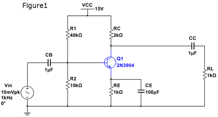
1265_Figure.png

Part B:

1. Download the "Lab troubleshooting" file and perform analysis for the circuits to locate the fault embedded in the circuit.

2. Step by step measure the key point's value with Agilent multimeter. Carefully analyze each measured value to locate the fault within the circuits. Fix the fault and with the corrected fault in the newly circuit, measure and record the new values.

Review questions:

1. Compare a calculated and measured values. Discuss whether the values are the same of different. If they are different, provide the reasoning.

2. Does the DC analysis confirm your calculations?

3. What is the gain of the amplifier? Does the gain obtained from analysis match the measured gain? If not, what is the problem and how would you fix it?

4. What is the role of capacitors in the AC analysis?

5. Did you find any clipping of the collector current? If so, how did you adjust the circuit to avoid clipping?

Deliverables:

1. DC and AC analysis of the circuit and all the calculations including gain of the amplifier from step 1.

2. Place your student ID card on the breadboard and take a picture of the circuit board and pin out on the NI myDAQ Instrument Device.

3. Take screenshots of the measurements obtained from function generator and Oscilloscope and Multimeter on the NI ELVISmx Instrument Launcher on your screen.

4. Screenshots of the measurements from DC analysis (without the capacitors). Screenshots of the measurements from AC analysis (with the capacitors). Screenshots of the input voltage Vin, base voltage VB and load voltage VRL.

5. Screenshots of collector voltage (Vc) (if any clipping).

6. Tabulate the data from analysis and measurements to confirm the gain of the amplifier.

Attachment:- Lab Assignment.rar

Electrical & Electronics, Engineering

  • Category:- Electrical & Electronics
  • Reference No.:- M92203527
  • Price:- $105

Guranteed 48 Hours Delivery, In Price:- $105

Have any Question?


Related Questions in Electrical & Electronics

Research report1 read 3 to 4 journal articles about

Research report 1. Read 3 to 4 journal articles about digital control or industrial control, eg. one particular application, implementation aspect such as selection of sampling time, hardware etc. No text book example is ...

Case studythis assignment consists of a written report of

CASE STUDY This assignment consists of a written report of approximately 1000 words and any diagrams in which you are asked to critically compare different process methods used to achieve the same result and show an awar ...

Questions -problem 1 - solve for i0 in fig using mesh

Questions - Problem 1 - Solve for i 0 in Fig. using mesh analysis. Problem 2 - Use mesh analysis to find current i 0 in the circuit. Problem 3 - Use mesh analysis to find v 0 in the circuit. Let v s1 = 120 cos(100t+ 90 o ...

Questions -q1 a single-phase transformer rated 21 kv130 v

Questions - Q1. A single-phase transformer rated 2.1 kV/130 V, 7.8 kVA has the following winding parameters: r1= 0.7Ω, x1 = 0.9Ω, r2 = 0.04Ω and x2 = 0.05Ω. Determine: a. The combined winding resistance ________ Ω and le ...

Problems -problem 1 - find v0 in the op amp circuit of fig

Problems - Problem 1 - Find v 0 in the op amp circuit of Fig. 1. Problem 2 - Compute i 0 (t) in the op amp circuit in Fig. 2 if v s = 4 cos(10 4 t). Problem 3 - If the input impedance is defined as Z in = v s /I s , find ...

Question 1 in the voltage regulator circuit in figure p221

Question 1: In the voltage regulator circuit in Figure P2.21, V 1 = 20 V, V Z = 10 V, R i = 222Ω and P z (max) = 400 mW. (a) Determine I L, I z , and I L , if R L = 380Ω. (b) Determine the value of R L , that will establ ...

Summative assessmentin 2017 sej101 assessment will consist

Summative Assessment In 2017 SEJ101 assessment will consist of nine tasks that will develop a portfolio of your assessed work. Throughout the trimester you will have the opportunity for feedback on all nine tasks before ...

Question 1 - for the transistor in the circuit shown in

Question 1 - For the transistor in the circuit shown in Figure, assume β = 120. Design the circuit such that I CQ = 0.15 mA and R TH = 200kΩ. What is the value of V CEQ ? Question 2 - (a) For the circuit shown in figure, ...

Nanotechnology engineering program assignment - passive

Nanotechnology Engineering Program Assignment - Passive Filters Q1) Determine what type of filter is in circuit shown. Calculate the cutoff frequency f c . Q2) Determine what type of filter is in circuit shown. Calculate ...

Nanotechnology engineering - resonance circuits questions

Nanotechnology Engineering - Resonance Circuits Questions - Q1) A series RLC network has R = 2KΩ, L = 40mH and C = 1μF. Calculate the impedance at resonance and at one-fourth, one-half, twice, and four times the resonant ...

  • 4,153,160 Questions Asked
  • 13,132 Experts
  • 2,558,936 Questions Answered

Ask Experts for help!!

Looking for Assignment Help?

Start excelling in your Courses, Get help with Assignment

Write us your full requirement for evaluation and you will receive response within 20 minutes turnaround time.

Ask Now Help with Problems, Get a Best Answer

Why might a bank avoid the use of interest rate swaps even

Why might a bank avoid the use of interest rate swaps, even when the institution is exposed to significant interest rate

Describe the difference between zero coupon bonds and

Describe the difference between zero coupon bonds and coupon bonds. Under what conditions will a coupon bond sell at a p

Compute the present value of an annuity of 880 per year

Compute the present value of an annuity of $ 880 per year for 16 years, given a discount rate of 6 percent per annum. As

Compute the present value of an 1150 payment made in ten

Compute the present value of an $1,150 payment made in ten years when the discount rate is 12 percent. (Do not round int

Compute the present value of an annuity of 699 per year

Compute the present value of an annuity of $ 699 per year for 19 years, given a discount rate of 6 percent per annum. As