Ask Question, Ask an Expert

+61-413 786 465

info@mywordsolution.com

Ask Other Engineering Expert

Lab Assignment: Bridge Rectifier

Introduction:

Lab is based on the previous lab on half-wave and full-wave rectifiers and taking that knowledge to build a bridge rectifier.

Materials and Equipment:

Materials:

• Simulated Parts (Multisim):

o 10:1 transformer (To access in Multisim under Master Database, in Group > Basic > Transformer > Select 1P1S)
o Two diodes 1N4001
o Two 2.2 kΩ resistors
o One 100 μF, 50 V electrolytic capacitor (any voltage rating is fine since is simulation only)
o One fuse (any rating is fine since is simulation only)

Equipment:

• Virtual Instruments (Multisim):

o Tektronix Oscilloscope
o Agilent Multimeter

• AC Power Source (To access in Multisim under Master Database > Group > Sources > Power Sources > AC_POWER)

Note: Multisim must be configured so a date and time stamp is visible in all simulations. Omission of the date and time stamp causes the lab to be worth only 1%. Please refer to the Procedure to view date and time stamp at the end of the lab.

1. Construct the bridge rectifier circuit shown in Figure 1. Double click the AC_POWER SOURCE and set the voltage value to 30Vrms. Notice that no terminal of the transformer secondary is at ground potential (some simulation software will not run if it is not connected to the ground, check yours). The input voltage to the bridge, VSEC, is not referenced to ground. Be sure to set the tolerance of the resistors to 10%. (Refer to the Tools and Templates section if you do not know how to set tolerances for resistors.)

2. Using the AC Power Source to provide VAC, run the simulation.

3. Use the Agilent multimeter to measure VSEC (rms) and then use the oscilloscope to measure the peak output voltage (VLOAD) without a filter capacitor. Be sure to take screenshots of your measurements showing the equipment, the circuit, the connections to the multimeter, and the date and time stamp.

4. Tabulate all data gathered.
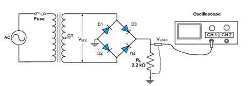
1841_Rectifier-Circuit.jpg
Figure 1

4. Connect the 100 μF capacitor in parallel with the load resistor. Measure VLOAD, the peak-to-peak ripple voltage VRIPPLE, and the ripple frequency. Tabulate all data gathered and compare the results with and without the filter capacitor.

Without the capacitor With the capacitor
Output load voltage VLOAD
Peak-to-peak ripple voltage VRIPPLE
Ripple frequency

5. Choose a diode among the four connected to the bridge and open it. Simulate an open diode in the bridge and explain what happens to the output voltage, the ripple voltage and the ripple frequency?

6. Investigate the effect of the load resistor on the ripple voltage by connecting a second 2.2 kΩ, 10% tolerance, and load resistor in parallel with RL and C1 in the full-wave circuit of Figure 3. Measure the ripple voltage. Be sure to capture the screenshots for the circuit and measured values with the date and time stamp (see procedure below). When taking screenshots of your measurements, make sure that the circuit is also visible with connections to the equipment. Multiple screenshots may be necessary to demonstrate the circuit setup and the measurements.

Review questions:

1. Explain how you could measure the ripple frequency to determine if a diode were open in a bridge rectifier circuit.

2. What is the maximum dc voltage you could expect to obtain from a transformer with a 3 Vrms secondary using a bridge circuit with a filter capacitor?

Deliverables:

1. Follow the template "Lab Report Template" to compile the report, and make sure to check the report against the grading rubric below. The template can be found in the "Tools and Templates" link in the left navigation panel. The template should provide places for you to include the analysis of the circuit/calculations, table, screenshots of the circuit and measurements, and the answer to the questions. Again, be sure the screenshots of the circuit and measurements, including the date and time stamp.

2. Make sure to include the table, calculations, screenshots of the measurements and the answer to the questions. Save the document as Lab2YourGID.docx (ex: Lab3G00000000.docx).

Procedure to view date and time stamp:

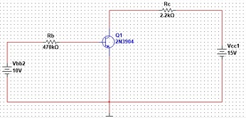
On the upper menu of Multisim, click "VIEW" then click "SPREADSHEET VIEW", click the "SIMULATION" tab on the bottom left of the screen. You will see the screen below with a date and time stamp of your simulation with the circuit design you created.
938_Circuit.jpg

Attachment:- Lab-Report-Template.rar

Other Engineering, Engineering

  • Category:- Other Engineering
  • Reference No.:- M92546785
  • Price:- $55

Priced at Now at $55, Verified Solution

Have any Question?


Related Questions in Other Engineering

Projection of planes1 a regular pentagon of 25 mm side has

Projection of Planes 1. A regular pentagon of 25 mm side has one side on the ground. Its plane is inclined at 45° to H.P. and perpendicular to the V.P. Draw its projections. 2. Draw the projection of a circle of 50 mm di ...

Assignment -problem 1 - given is the lcc difference

Assignment - Problem 1 - Given is the LCC difference equation that represents some LTI system: y(n) - ¾y(n-1) - ¼y(n-2) = x(n) + x(n-1)   a) Find the impulse response of the system (solve the LCCDE). b) Draw a block diag ...

Engineering analysis homework -for every problem provide

Engineering Analysis Homework - For every problem, provide The MATLAB script/function files that solve the problems. Problem 1: Write a script that solves the problem. For (c), show results of the evaluation of every ind ...

This is your second design assignment this assignment

This is your second design assignment. This assignment requires you to design a complex state machine. You are designing a digital alarm clock. There are various designs you can attempt. More complex designs are worth mo ...

1 online discussion forum - post your proposed topic and

1. Online Discussion forum - Post your proposed topic and chosen data set as well as a short plan for the project. This is required for approval of the topic. As discussed, students must select unique topics, therefore i ...

Assignment 11 what is the purpose of ore reserve and

ASSIGNMENT 1 1. What is the purpose of ore reserve and resource estimation? Why are resource and reserve estimates important to the mining industry? 2. What is meant by ore? What is meant by the term waste? How is the di ...

Question - show that the zero-point energy of a simple

Question - Show that the zero-point energy of a simple harmonic oscillator does not contribute to its entropy or heat capacity, but does contribute to its energy and Helmholtz function.

Engineering analysis assignment -for every problem provide

Engineering Analysis Assignment - For every problem, provide The MATLAB script/function files that solve the problems. Problem 1: Plot the function f(t) = (x+5) 2 /(4+3x 2 ) for -3 ≤ x ≤ 5. using plot command. Use the ar ...

Load fault level analysis amp protection design of a remote

LOAD, FAULT LEVEL ANALYSIS & PROTECTION DESIGN OF A REMOTE AREA MICROGRID Assignment Please undertake the following analyses: 1. Calculate the 3-phase fault levels on Bus 2, Bus 3 and Bus 4 with the main supply connected ...

Question 1 define rock mechanics discuss the main

Question 1 . Define rock mechanics. Discuss the main objectives of the application of rock mechanics in mining. Question 2. Define stress. Draw a diagram and define the normal and shear stress by resolving the resultant ...

  • 4,153,160 Questions Asked
  • 13,132 Experts
  • 2,558,936 Questions Answered

Ask Experts for help!!

Looking for Assignment Help?

Start excelling in your Courses, Get help with Assignment

Write us your full requirement for evaluation and you will receive response within 20 minutes turnaround time.

Ask Now Help with Problems, Get a Best Answer

Why might a bank avoid the use of interest rate swaps even

Why might a bank avoid the use of interest rate swaps, even when the institution is exposed to significant interest rate

Describe the difference between zero coupon bonds and

Describe the difference between zero coupon bonds and coupon bonds. Under what conditions will a coupon bond sell at a p

Compute the present value of an annuity of 880 per year

Compute the present value of an annuity of $ 880 per year for 16 years, given a discount rate of 6 percent per annum. As

Compute the present value of an 1150 payment made in ten

Compute the present value of an $1,150 payment made in ten years when the discount rate is 12 percent. (Do not round int

Compute the present value of an annuity of 699 per year

Compute the present value of an annuity of $ 699 per year for 19 years, given a discount rate of 6 percent per annum. As