Ask Other Engineering Expert

Assignment- Digital Fundamentals

Laboratory- Introduction to 7404 Hex Inverter & Basic Gates & Timing Diagrams

The purpose of this laboratory experiment is to:

I. Get practice in wiring integrated circuits on the trainers
II. Generate "Truth Tables" for basic gates.
III. Use these logic elements to generate a high level logic element.
IV. Generate the "Truth Table", and identify the logic element.
V. Generate timing diagrams for the basic gates.

Part A: Introduction to 7404 Hex Inverter (IC)

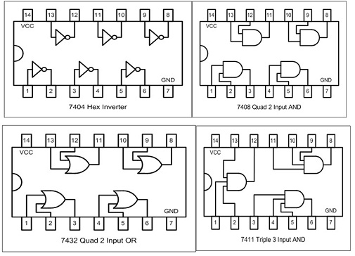
Hook up the 7404 Hex Inverter integrated circuit, and look at the input and output of ONE of the inverters (pins 1 and 2). Note: There are 6 inverters in the same package, hence the term Hex. See pin-outs of the 7404 Hex Inverter at the last page.

361_Pin-outs of the 7404.jpg

A-1) Using the built in signal generator (RED Trainer), place a 1 kHz and TTL input to the inverter. [Be sure to connect the IC (pin 14) to 5VDC and (pin 7) to the ground (GND)].

Look at the input and output together on the scope using 2 Volts DC per division. Draw what you see:

Output Waveform

Input Waveform

Note: Label the x-axis and y-axis

A-2) What is the period? ________________milli-seconds
A-3) Use 5.0 VDC per division on the scope, then read the following on the scope. Draw what you see below.

Voltage amplitude of input=____________

Voltage amplitude of output=____________

Frequency of input=____________

Frequency of output=____________

Period of input=____________

Period of output=____________

Note: Label the x-axis and y-axis

Part B: Basic Gates & Timing Diagrams

A Truth Table consists of all possible logic inputs and the output that corresponds to each logic input.

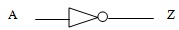
In the following, an AND Gate with logic inputs A & B with a logic output Z is shown:

1222_Logic Output Z.png

A input

B input

Z output

0

0

0

1

0

0

0

1

0

1

1

1

The timing diagram is discussed at length in Chapter 3. The basic timing diagrams for the logic gates we are using in this lab allow for a visual reading of how the logic functions. By viewing the timing diagram, the reader can see what outputs result from the different possible combinations of inputs. The truth table can easily be determined by looking at the basic timing diagram.

B-1) Follow steps of part A-1 to hook up the 7408 of Quad 2-Input AND gate, then connect input A to SW7 and input B to SW6 then generate a truth table below by measuring output Z using voltmeter. Connect a wire from the output pin to any of the 8 bits LED display located on the upper right corner of the function generator. Note: There are 4 AND gates in the same package.

1222_Logic Output Z.png

Input A

Input B

output Z

0

0


1

0


0

1


1

1


B-2) Connect a 1 kHZ, TTL to input A and keep input B connected to SW6. First, put a "1" on input B. Look at input A, the square wave, and the output of the AND using an oscilloscope. Second, put a "0" on input B. Look at input A, the square wave, and the output of the AND using an oscilloscope. Draw both cases on the graph below

First case (input B=1)
Draw the input & the output

Second case (input B=0)

Draw the input & the output

Note: Label the x-axis and y-axis

B-3) Follow steps of part B-1 to hook up the 7432 Quad 2-Input OR gate, and generate a truth table. Note There are 4 OR gates in the same package.

A input

B input

Z output


B-4) Connect a 1 kHZ, TTL to input A and keep input B connected to SW6. First, put a "1" on input B. Look at input A, the TTL, and the output of the OR gate using an oscilloscope. Second, put a "0" on input B. Look at input A, the TTL, and the output of the OR gate using an oscilloscope. Draw both cases on the graph below.

First case (input B=1)
Draw the input & the output

Second case (input B=0)

Draw the input & the output

Note: Label the x-axis and y-axis

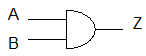
B-5) Hook up the 7411 Triple 3-input AND gate, and generate a truth table. Note: There are 3 AND gates in the same package.

Note: To turn on any gate pin7 has to be grounded and pin14 must be connected to +5V DC power supply.

1949_Logic Output.jpg

A input

B input

C input

Z output


B-5) Hook up the following circuit and generate a Truth Table.

1411_Logic-Circuit.jpg

A input

B input

Z output


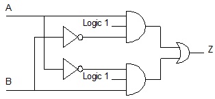
Can you identify this logic element? ____________________________________

Write-up: Review and follow the lab write-up guidelines. Show me your work before you leave.

2237_IC-7404,7408,7432_and_7411.jpg

Other Engineering, Engineering

  • Category:- Other Engineering
  • Reference No.:- M92197589

Have any Question?


Related Questions in Other Engineering

Register design a cpu register is simply a row of

Register design A CPU register is simply a row of flip-flops (i.e. SR, JK, T, etc) put side by side in an array to make the size of register required. For example, an 8 bit register has 8 flip-flops side by side for stor ...

A detailed review of spatial modulation and simulation

A Detailed Review of Spatial Modulation and Simulation Learning Outcomes a. Learn how to model mobile communication channels d. Discern knowledge development and directions on the recent advances in 4G to the research pr ...

Mine safety amp environmental engineering assignment -part

Mine Safety & Environmental Engineering Assignment - Part 1 - Questions 1. Occupational health and safety is the primary factor that needs to be considered in the mining industry. Discuss this statement. 2. Define the fo ...

Projectflow processing of liquor in a mineral refining

Project Flow Processing of Liquor in a Mineral Refining Plant The aim of this project is to design a flow processing system of liquor (slurry) in a mineral (aluminum) refining plant. Aluminum is manufactured in two phase ...

Learning outcomes evaluate multiuser communication and

Learning Outcomes Evaluate multiuser communication and resource sharing techniques; Apply the techniques of, and report on, digital communication applications using Matlab and hardware devices. Assignment Description The ...

Operations engineering assignment -please select only one

Operations Engineering Assignment - Please select only one of the following case studies for your assignment: CASE A. Tesla Motors Tesla is an innovative manufacturer that designs, assemble and sells fully electric vehic ...

Select a risk problem from the list below and prepare a

Select a risk problem from the list below and prepare a risk management plan in accordance with AS/NZS ISO 31000:2009. Please ensure that: - Establish the context clearly, in accordance with the Standard; - Define your s ...

Engineering materials term paper assignment -conduct a

ENGINEERING MATERIALS TERM PAPER ASSIGNMENT - Conduct a thorough literature search and write a 15-20 page technical review paper on the evolution of the engineering materials used in the manufacturing of any one of the f ...

Task 1using the lab kit design a circuit for the processor

Task 1: Using the lab kit, design a circuit for the processor to control the output of a connected 7-segment LED display device. You will be provided with a standard common anode 7-segment display of the type FND-507 (or ...

Control theory - lab reportsfor experiments 1 to 4 you must

Control Theory - Lab Reports For experiments 1 to 4 you must undertake the following: a) At the start of each section (including the pre-lab activities) there are a number learning outcomes. That is, what students should ...

  • 4,153,160 Questions Asked
  • 13,132 Experts
  • 2,558,936 Questions Answered

Ask Experts for help!!

Looking for Assignment Help?

Start excelling in your Courses, Get help with Assignment

Write us your full requirement for evaluation and you will receive response within 20 minutes turnaround time.

Ask Now Help with Problems, Get a Best Answer

Why might a bank avoid the use of interest rate swaps even

Why might a bank avoid the use of interest rate swaps, even when the institution is exposed to significant interest rate

Describe the difference between zero coupon bonds and

Describe the difference between zero coupon bonds and coupon bonds. Under what conditions will a coupon bond sell at a p

Compute the present value of an annuity of 880 per year

Compute the present value of an annuity of $ 880 per year for 16 years, given a discount rate of 6 percent per annum. As

Compute the present value of an 1150 payment made in ten

Compute the present value of an $1,150 payment made in ten years when the discount rate is 12 percent. (Do not round int

Compute the present value of an annuity of 699 per year

Compute the present value of an annuity of $ 699 per year for 19 years, given a discount rate of 6 percent per annum. As