Aircraft Front Landing Gear Linear Actuator Design
Your team's (group of 4 students) task is to design a linear actuator that can lower and raise the front landing gear of an aircraft. The linear actuator will use a power screw that is driven from a hydraulic motor via a gearbox. The hydraulic motor specifications are documented below. Your team must design the entire gearbox and power screw actuator that is mounted between the fuselage and landing gear linkages, as illustrated in the image below.
The complete design will need to include the following:
- Load calculations
- Gear sizing
- Bearing specification
- Shaft design
- Gearbox housing design
- Power screw sizing
- Fastener size specification
- And designs of any other fixtures or housings that you require
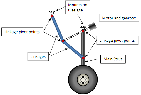
Figure 1. Schematic of front landing gear linkages/assembly
The power screw is attached to the hydraulic motor via a gearbox for the correct torque input to drive the power screw. The (blue) linkages in Figure 1 are attached to the end of the power screw and the ‘nut' of the power screw is attached to the top pivot of the main landing gear strut. Turning the power screw translates the nut along the power screw, which in turn rotates the main landing gear strut about the top pivot for retracting or raising the landing gear. The main strut and (the upper blue) linkage are attached to the fuselage as illustrated.
The linear actuator, which comprises of the power screw, nut, pivot attachments, housing(s), gearbox and hydraulic motor should be designed as one single device that can be installed onto the landing gear mechanism. As a result, the linear actuator housing is structural and reacts the motor drive torques as well as forces during landing gear retracting or raising. Rotating motion between components should be isolated with rolling element bearings that are adequately sized. There is no requirement for coaxial alignment between the power screw and motor.
The aircraft is designed to operate as reliably as possible to avoid any incidents, however, this must be within reason to avoid unnecessary weight. As a result, minimum safety factors should be 2 where required.
The landing gear is specified to be lowered or raised at a maximum speed of 250kmh, and maximum altitudes of 2000ft. For simplification, the landing gear strut can be assumed negligible and the wheels are considered the main contributor to the drag forces on the entire mechanism; likewise the weight of the assembly can be neglected. Further, the system is locked when fully retracted and as a result the linear actuator is isolated from wheel braking loads and vertical loads. There are two wheels adjacent to one another with the main strut running between the wheels, where the wheels have a drag coefficient of 3. The aircraft manufacturer has stated that the front landing gear must retract or raise within 10 seconds (maximum), where the bottom of the fuselage is 550mm below the main strut pivot. The link lengths and other associated dimensions are illustrated in Figure 2 below.
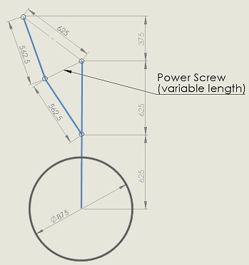
Figure 2. Illustration of the key landing gear dimensions (in mm)
The front landing gear wheels (Figure 1 and 2) are 875mm in diameter and 320mm wide.
The hydraulic motor (Figure 3) has a maximum operating capacity of 5Nm torque and 3000RPM, and overall dimensions (ONLY!) equivalent to the TB0036 hydraulic motor found in the attached Parker hydraulic motor documentation
Notably, different mounting flanges and output shaft options (including dimensions) are available within the documentation. You are free to select any of the flange and output shaft styles based on which best suits your design. Your gearbox design must be able to attach the TB0036 motor (hint: the gearbox housing and input coupling/gear must match the motor mounting flange and output shaft respectively).
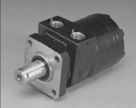
Figure 3. Sample hydraulic motor illustration (Note: output shaft and mounting flange may vary)
The overall linear actuator design should include power screw design, nut design, gear design, shaft design, fastener sizing (where necessary), bearing selection (and any accompanying components such as seals and clips, etc.) and housing(s) to ensure a completely operating actuator. Fastener calculations are required to justify the size of any main structural bolts used in the design. It is a design requirement that any rotating structural components in the design are located by rolling element bearings.
Notes and Assumptions:
I. Neglect main strut drag and landing gear weight
II. Ignore thrust bearing friction on the power screw
III. Assume 0.1 friction coefficient between nut and screw of the power screw
IV. Assume there is no loss in aerodynamic drag as the wheel retracts into the fuselage
V. Assume that the hydraulic motor has a constant power curve
VI. The gearbox should be serviceable
VII. The gearbox should include oil fill and drain locations
VIII. This gearbox should be designed for an aeronautical application
IX. The final design should be a complete ready-for-manufacture design
The assignment deliverables for the design are as follows:
1. A complete set of design documents for the assembly:
- A design report that details:
- Product design specification
- Manufacturing details (including processes, off-the-shelf components, required treatments, etc.)
- An analysis report that covers:
- Load calculations (prior to further analysis)
- Strength calculations
- Failure analysis calculations of component(s)/assembly where applicable
- Finite Element Analysis of structural components
- A complete set of manufacturing drawings - fully dimensioned of all parts ready for manufacture (Note: this excludes the motor, gear tooth profiles and bearings)
- SolidWorks 3D model (or equivalent CAD model that can be opened within SolidWorks) of the complete actuator assembly and components. Printed (hardcopy) images of all the components in your design are required along with electronic files of the parts and assemblies
2. Presentation: An informal 5 minute presentation of your group's design to the class during the final lecture.
3. Teamwork: Cooperate as an effective team with suitable load sharing
4. Report: All aspects for a quality report, such as grammar, referencing, presentation, etc.
Note: The written component (excl. drawings) of the design report should not exceed 10 pages, any content beyond 10 pages will not be considered in the mark. The analysis report should not exceed 30 pages, any content beyond 30 pages will not be considered in the mark.